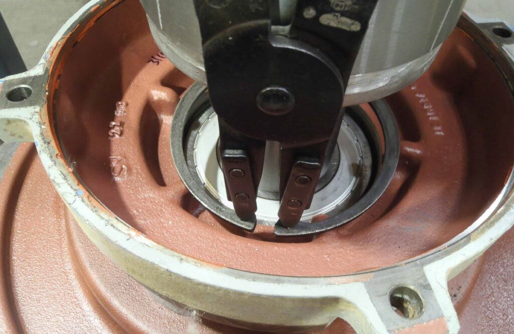
The bearings of an electric motor are normally removed using a bearing puller. It has jaws to grab the back of the bearing and the threaded rod of the puller mounted at the end of the shaft. When tightened, the bearing got pulled out of the bearing journal
There are times when you face the task of removing and changing the bearing of a motor but either your puller won’t fit or you just don’t have it.
There are other ways to do it and here are some of them.
1. Using a vise and a pair of pry bar
2.. Cutting the outer race and then applying heat to the inner race of the bearing
3. Using a bearing splitter
4. Using the lathe machine and its coolant
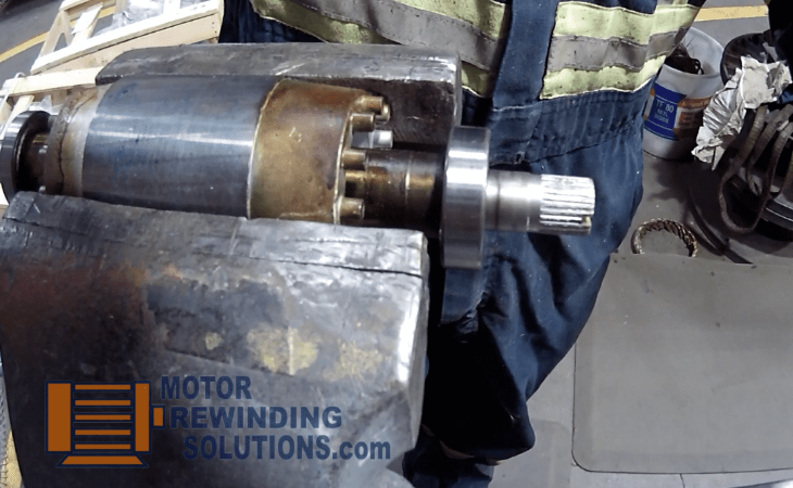
I. Removing a rotor bearing using a vise and a pair of pry bar
This method of removing the bearing is fast but it is necessary that the vise is securely mounted on a workbench. .
a) Clamp the rotor in a vise. Align the edge of the vice jaw to the rotor bearing.
Aligning the rotor bearing on the vise jaw
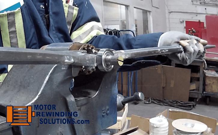
b) For small bearings sizes 6203, 6202, 6201 or smaller, you can use a pair of longer, flat tipped screwdrivers, with the same length if possible. For bigger bearings sizes 6204 and 6206, a pair of pry bars are appropriate.
c) If the shaft is rusty, polish it up first using emery cloth then spray it with lubricant.
d) Pry the bearing out.
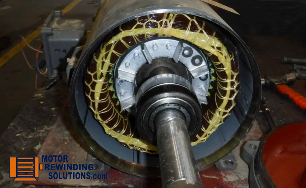
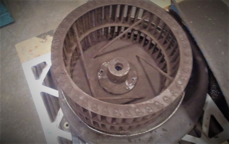
Some rotors have an internal fan made of aluminum, and the bearing is right behind it. Mount the rotor on the vise in a way that the fins of the fan are butting on the vise jaw to avoid damaging the fan. Pry the bearing out
Prying out the bearing of a rotor mounted on a vise
II. Removing the bearing by cutting the outer race then applying heat to the inner race.
There are cases where removing a bearing is not possible with a puller like when there is no room for the puller jaw or prying it out can be challenging when the bearing is beside a flimsy fan. Heating the bearing will be your option
Bearings have an inner race which is tightly fitted in the shaft and an outer race that spins. Steel expands when heated so if the bearing inner race is hot and the shaft is cold it just slides out.
The heating process has to be fast otherwise the shaft will also heat up and both of them will expand. The bearing then will still be tightly held in place on the shaft.
In this case, you have to redo the process by cooling down the whole rotor first and then try heating the bearing again.
Procedure of removing a bearing using heat.
a) Secure the rotor in a vise
b) Using a thin disk grinder, cut the outer race of the bearing in two places until it falls off together with the balls. For smaller bearings you can use a Dremel tool.
On bigger bearings, you can use a cutting torch but make sure to cut it off to the side so that the molten metal will not fall on the shaft.
c) Let the rotor and the bearing inner race cools down. Put a fan.
d) Using a torch, heat the bearing inner race. You can use either oxyacetylene torch or a portable MAPP torch.
e) With your Kevlar heat resistant gloves on, pull the bearing out otherwise use a small piece of metal to gently slide the bearing inner race out of the shaft.
f) On bigger bearings, if you position the rotor upside down, the bearing inner race will probably just fall off.
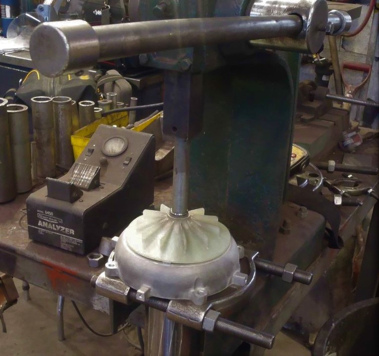
III. Removing the bearing from the shaft using a bearing splitter plate.
One advantage of a bearing splitter is that you can remove bearings fast. I can tell you that because I use the arbor press instead of the puller attachment that sometimes comes with the splitter.
If you have an arbor press and a bearing splitter plate, you can literally remove a bearing in less than 10 seconds. That fast.
Second advantage of it is that if the bearing is too close to the fan that even a puller jaw won’t fit.
Splitter plate can be thin enough to fit behind those bearings.
The third advantage is when the bearing to be removed is fairly new and needs to be reused.
For example, a brand new bearing was installed only to realize that a snap ring has to go behind it. It has to be removed and the snap ring installed first before the bearing.
Normally, since the bearing is cheap we just replace it with a new one. Besides, when you use the puller, the seal gets damaged.
Not so with the bearing splitter. Its flat surface puts even pressure on the inner and outer race of the bearing. Although replacing it is still ideal.
Procedure in using a bearing splitter and a press to remove rotor bearings
a. Loosen the splitter bolt nuts until the splitter plate clears the diameter of the bearing.
b. Set the bearing splitter flat side up on the arbor press base.
c. Position the bearing on the splitter
d. With one hand on the arbor press’s lever arm and the other holding the rotor, press the bearing out of the shaft.
The process can also be made faster by keeping those nuts loose. In this way, you can easily position the bearing on the splitter, close the two plates together, and press the bearing out.
Another suggestion is to put a spacer between the rotor shaft and the arbor press ram shaft so that the position of the arbor press lever is at the ideal spot where you can get a good leverage
The disadvantage is that you need two people to remove bearings on a bigger rotor because of its weight.
Also, some arbor press designs are not suited for this purpose. The base should have an opening that can accommodate the diameter of the rotor.
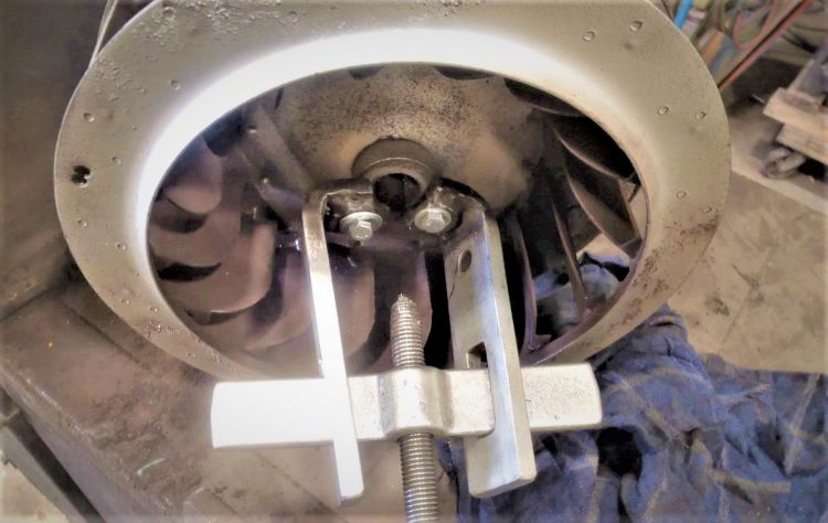
Pressing out the bearing using a bearing splitter mounted on an arbor press
If a motor repair shop does a lot of rotor bearing replacements, modifying the base of the arbor press can be functional and productive.
For DIYers who don’t have an arbor press, setting the splitter on two blocks of wood and tapping the shaft with a rubber mallet to remove the bearing will also work.
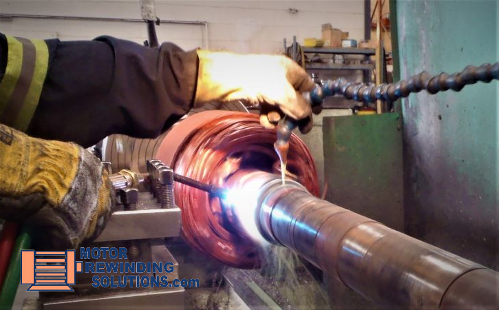
IV. Removing the bearing from the shaft using heat and lathe coolant.
Removing the bearing stuck in the rotor shaft using a puller and oxyacetylene torch can be challenging if the bearing journal is already damaged, corroded, or oversized.
Bearing balls can also collapse making a puller useless or in cases where the outer race of a roller bearing comes off leaving the inner race on the shaft.
Heating the bearing inner race evenly white rotating and making use of the lathe coolant is one option.
Also, when you have to set the rotor on the lathe to measure the shaft runout, might as well remove the bearing there.
Procedure in removing stubborn bearing out of a rotor shaft
a. Cut the bearing outer race using a cutoff disk grinder or oxy-acetylene cutting torch if not out already.
b. Set up the rotor on the lathe.
c. Set the lathe speed to around 45 RPM and let it run.
d. Turn on the lathe machine coolant and point the hose tip to the rotor shaft about an inch and a half (3.8 cm.) away from the bearing inner race.
e. Heat the bearing inner race using the rosebud tip of an oxyacetylene torch.
f. When the bearing comes hot, you can just slide it out.
Removing bearing inner race using lathe machine coolant and oxyacetylene torch
There are other practical ways for sure that other motor mechanics use to remove bearings without a puller
If you have a problem with your electric motor or you want me to post a particular subject about it, please write it on the comment section and I’ll be happy to post it for you.
If you have other ideas, please share them below in the comments section so that others may benefit from it. I’m sure there’s a lot more ways to remove a bearing from the shaft besides a puller.
Electric motors are used to run machinery, pumps, compressors, blower fans, and all other kinds of equipment. Without motors, none of these machines will move.
The shafts of the electric motors are coupled to these machines using some kind of attachment. It could be a sheave (pulley), a coupling, or a mounted gear.
When electric motors are up for repair, it has to be disassembled and parts that are defective need to be repaired.
The end bell also called the end shield or end cap of the motor cannot be removed and bearing housing inspected if there is something attached to the shaft.
This post includes:
Steps on how to remove gear from electric motor shaft
Steps on how to remove a sheave (pulley) from an electric motor shaft
Tips on how to remove a coupling from an electric motor shaft
Tools you need to remove gear, coupling, and sheave (pulley). What to do if you don’t have them.
7 Steps on how to remove gear from The electric motor shaft
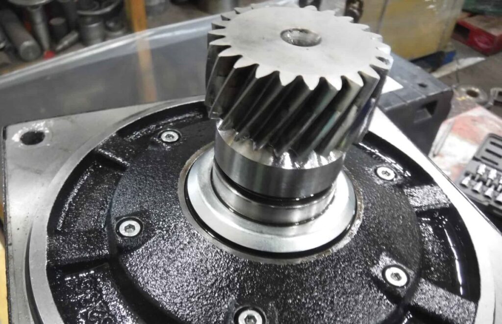
Electric motor shafts with helical gears are used on conveyor motors, roller motors, and gearbox motors while spur gears are commonly used on the motor as a spline for its brake or clutch.
Spur gear on the shaft used as spline for electric motor brake
Here are the steps:
Before removing gear from the motor shaft, measure the distance of the gear to the end of the shaft. This is so that you can reinstall it back at the same position later. Not unless it rests on a shoulder and/or a snap ring.
Check and remove anything that holds the gear to the shaft like a set screw or a snap ring. Sometimes a snap ring covered with grease is hard to see.
Helical gear held by a snap ring on an electric motor shaft
3. To remove gear from the shaft, use a two-jaw or a three-jaw puller.
4. When a gear is tight that the jaw keeps on disengaging, use a chain grip. This will keep the puller engaged.
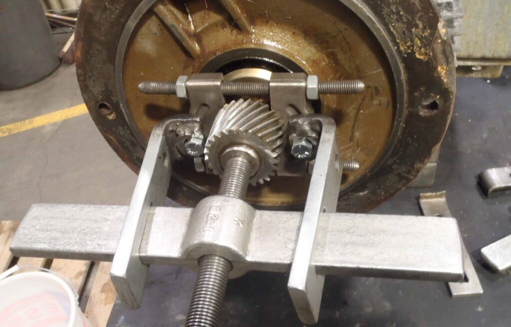
5. Another way is to use a bearing separator and a bar-type puller. Position the bearing separator behind the gear, screw in the threaded rods of the puller, and remove the gear.
Electric motor gear removal using a puller
To remove a gear without a puller, use the rosebud tip of an oxyacetylene torch and heat the gear. As soon as it is hot, lightly tap it out.
Use leather gloves and a face shield when using oxyacetylene
You can also use an arbor press if you are working on a small motor and the diameter of the end bell will fit the press. Put a bearing separator behind the gear and press the gear out using the press.
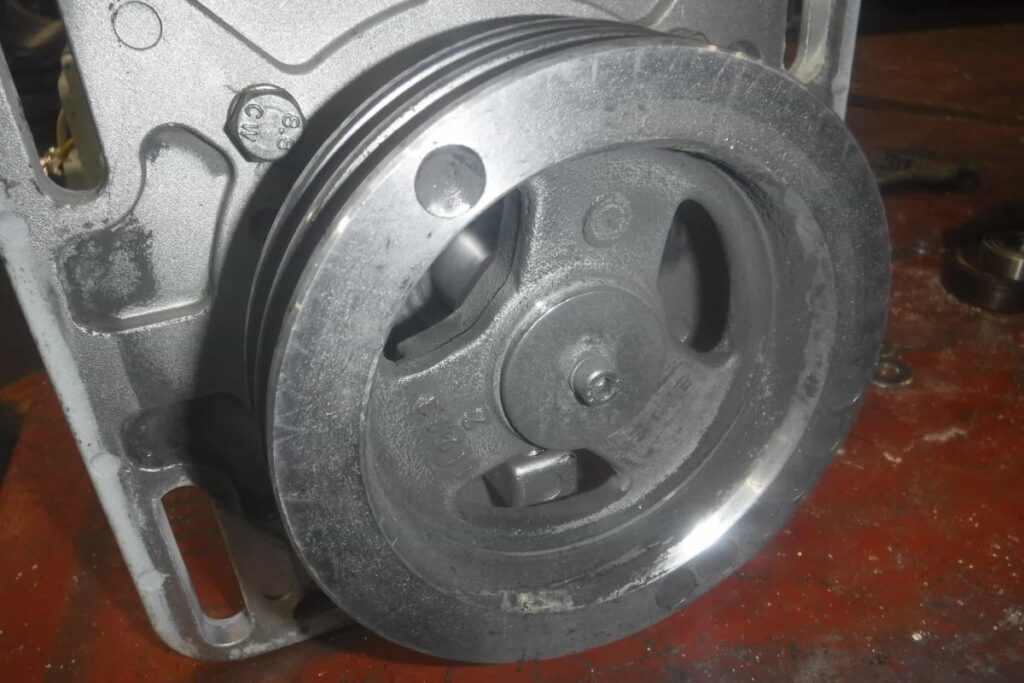
Removing a sheave (pulley) from the electric motor shaft
Sheave held on to the shaft using a key and bolt with washer
Some machines are coupled to the motor using v-belts and at times flat belts.
Sheave (pulley) is installed to the shaft either directly or through a hub or bushing.
Electric motor sheave pulley with a bushing Is a two-part assembly. Pulley is first unbolted and removed from the bushing then the bushing is removed from the shaft.
Some pulleys have no bushing. It is only held to the shaft by a key and two set screws
This is how to remove pulley or sheave from the electric motor shaft:
1. Before removing the sheave pulley from the motor shaft, measure its distance to the end of the shaft. This is so that you can reinstall it back at the same position later
2. If it is held by a bushing, measure the face of the bushing to the end of the shaft.
3. Check for set screws and remove them.
4. Pulley is usually bolted onto the bushing using four bolts. It also has two threaded holes to accommodate the jacking bolts for easy removal of the pulley. Remove the bolts.
5. Spray the pulley, the bushing, and the shaft with an oil lubricant.
6. If the shaft is rusty, use an emery cloth or sandpaper to remove and clean the shaft.
7. Get two from the bolts that you have removed, and install them on the two threaded holes on the sheave pulley. If the bolts are short, replace them with longer ones. Use this as jacking bolts
8. Tighten these two bolts to remove the pulley. The bushing is tapered, so the pulley should just pop out.
9. The bushing has a sliding fit to the shaft but because of corrosion and the key, it could be tight. One way of removing it is by the puller.
10. Another way of removing it is by jamming a screwdriver on the split of the bushing. This will allow for the bushing to increase its diameter for easy removal from the shaft. For pulleys that do not have bushing, use either a two-jaw or three-jaw puller to remove it.
11. Do not grab it by the pulley groove or you will break it. Some pulleys have bolt holes to accommodate the puller.
12. For pulleys that don’t have bushing, you can also use a bearing splitter and position it behind the pulley. Put the puller jaw behind the splitter to remove the pulley.
13. If that doesn’t work, use heat. Heat the pulley using the rosebud tip of oxyacetylene and soon as the pulley is hot, it should just slide out of the shaft. Be cautious, it’s hot.
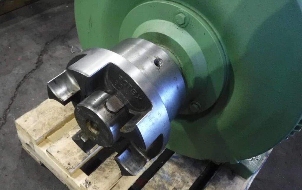
5 tips on how to remove a coupling from an electric motor shaft
Shaft jaw coupling held by a key and set screws
1. Before removing the coupling from the motor shaft, measure its distance to the end of the shaft. This is so that you can reinstall it back at the same position later. The coupling could be flush to the end of the shaft, out, or in by a certain distance. Make sure you take note of the position or have a picture.
2. Check for set screws and remove them
3. Use a puller to remove the coupling.
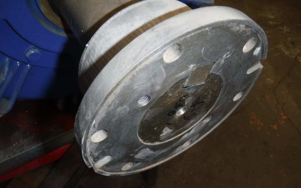
A shaft flange coupling with a key and set screws (not shown)
4. Most couplings are a tight fit. If you’re having a hard time with the puller, combine it with heat. While the puller is engaged, heat the coupling using the rosebud tip of the oxyacetylene and soon as the temperature reaches about 300C, continue pulling it out with the puller
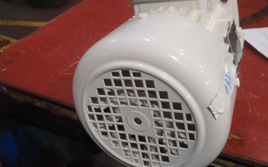
Most electric motors have an external fan. It’s a way of cooling the motor, especially the enclosed motor with no air vents.
The term is TEFC which stands for totally enclosed fan cooled motors.
Not unlike the bigger U-frame of older motors, nowadays, they are compact.
The same horsepower motors are built in smaller frames and even designed for higher efficiency. The result is they run warmer that is why they have a cooling fan
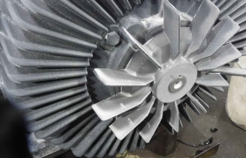
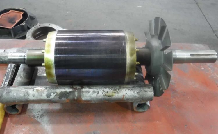
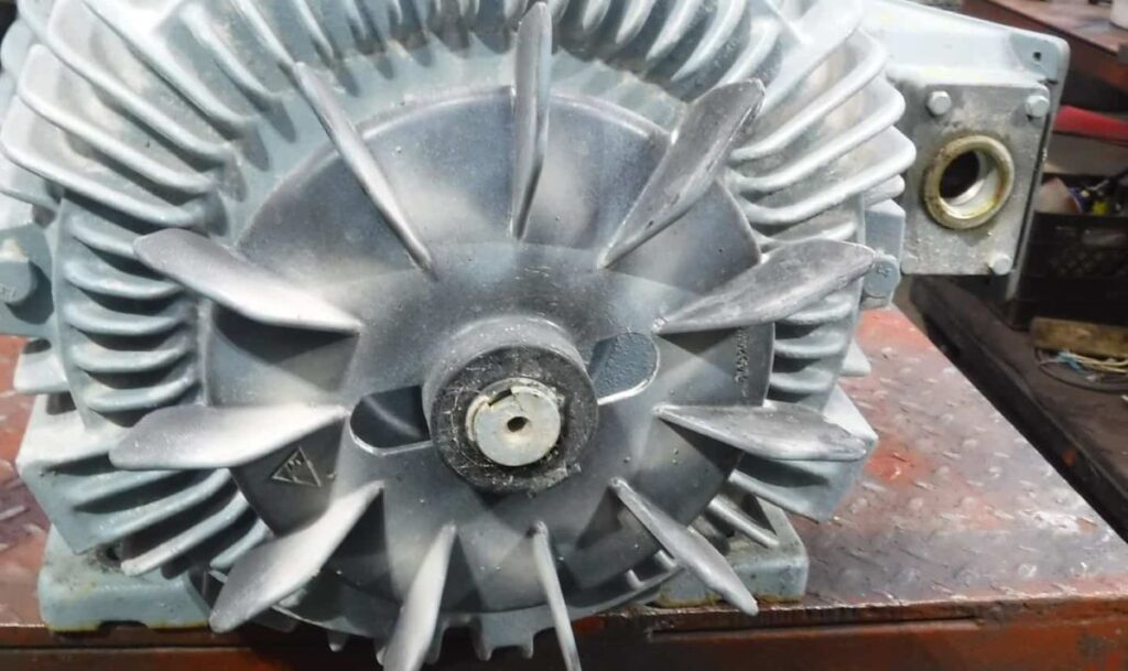
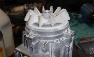
Besides external cooling fans, some motors of Baldor and Toshiba have internal cooling fans. These fans are meant to directly cool down the windings inside the motor.
Internal fan of an electric motor
Fans are commonly made of plastic although they can also be made of aluminum or cast iron.
They are also held in the shaft several ways. Some are set screws, some are clamps, and some by using a snap ring.
Fan with integrated clamp and tightening screw
For example, Siemens uses a built-in plastic tab to lock the fan in place. You have to insert in this tab a strip of thin metal and the fan can be pried out easily.
10 tips on removing the fan of an electric motor.
1. Take note also how far the fan is from the end of the shaft so you can put it back the same way
2. Small plastic fans are usually held in place either by a snap ring or a clamp. Remove it and spray the shaft with a lubricant
3. Pry the fan out making sure that the tip of the pry bar is as close as possible to the base of the fan closest to the shaft. This is to avoid breaking the fan.
4. If the fan is too close to the end bell (end shield) and the pry bar won’t fit, use two long screwdrivers with a flat tip.
Image of fan too close to the motor end bell
5. If it’s so close to the end bell that even a screwdriver won’t fit, try these three methods:
.
Method 1
Remove all the end bell bolts
Get a center punch or any steel drift smaller in diameter and put it at the center of the shaft where the fan is.
Image showing how to remove the rotor and the fan by driving a center punch in the middle of the shaft
Using a mallet and the center punch, drive the shaft going to the opposite end until the fan comes out.
Do not let the rotor fall off the table
Method 2
Remove the end bell (end shield) that doesn’t have the fan.
Separate the rotor with the fan still attached from the stator.
Use an arbor press to remove the end bell and the fan at the same time.
Image showing shaft being pressed out using arbor press to remove the fan
If there’s no arbor press, use blocks of wood, center punch, and a hammer.
Put the end bell fan side up on the blocks of wood with the shaft above ground.
Have someone support the rotor while tapping the rotor shaft out of the end bell and the fan.
Method 3
With the fan still on the shaft, separate the end bell from the stator, by tapping the drive end shaft.
Using a three-jaw puller, remove the end bell out, dragging the fan out with it.
6. As I mentioned some Siemens motors have a tab locking the fan through the groove on the shaft. Insert two thin strips of metal on those tabs and the fan can then be pried out.
Electric motor fan with locking tab
7. Bigger plastic fans are held in place by a clamp. Loosen it up by unscrewing the bolts. Some clamps need a pair of pliers to remove and some have screws.
8. Again, pry out the plastic fan using two pry bars keeping the tip of the pry bars as close as possible to the base of the fan closest to the shaft to avoid damaging it.
9. Some plastic fans have openings to accommodate a small puller. Use the puller to remove the fan although setting it up takes a bit longer compared to just prying. Don’t forget to spray it with lubricant.
10. Bearing separator also works by placing it behind the fan then use the puller to remove the fan.
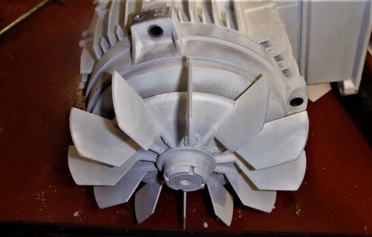
6 steps in removing the aluminum fan from an electric motor shaft
Most of the time you need heat to remove aluminum fans from the electric motor shaft. This is how you do it.
1. Remove the set screws holding the fan to the shaft.
2. Spray the shaft with lubricant and remove visible rust and corrosion from the shaft using emery cloth
3. Try and pry the fan out first. If it doesn’t want to go, use a puller
4. Sometimes there are openings to accommodate a small two-jaw- puller or bolt holes to bolt the puller jaws to the fan. It is not advisable to use the puller jaw on the outside diameter of the fan. You’ll break it.
Holes are provided on some fans to accommodate 2-jaw bearing puller
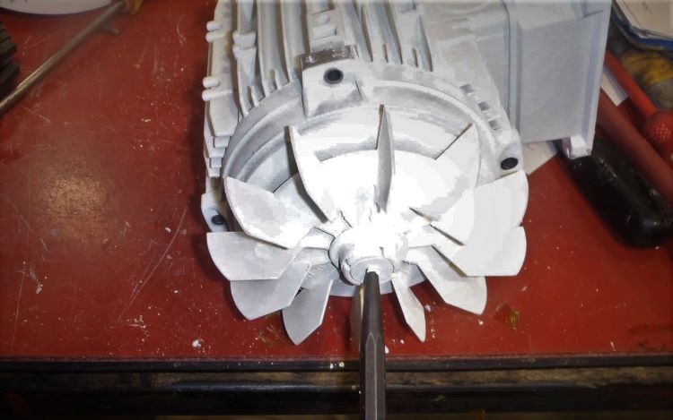
5. You can also use heat. Using either oxy-acetylene or a propane torch, heat the base of the fan. Do not heat the shaft. The idea is to expand the fan bore with heat while the shaft is cold.
6. Pry the fan out.
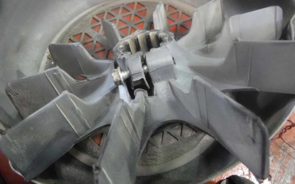
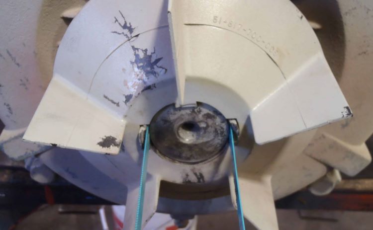
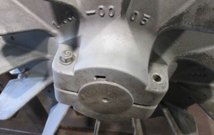
how to Remove a cast iron fan of larger motors
Most larger motors 100 horsepower and up have cast iron fans. To remove them,
1. Totally remove the bolt on the hub of the fan. Remove also the snap ring if there is any.
2. Most cast iron fans have a split hub. Insert a flat screwdriver on the split
Electric motor fan with a split hub
3. Insert and gently tap the screwdriver in the hub split until the fan loosens out
4. Pry the fan out. .
9 steps in removing a blower fan from the shaft of electric motors
Blower fans are easy to install when brand new. The set screws when tightened during installation sometimes create a nick on the shaft making it hard to remove
Blower fans are also ignored like it’s a maintenance-free unit. They’re not. They have to be maintained.
A Blower fan of an electric motor
Fan accumulated with dirt caused it to be out of balance. They will then vibrate, create noise, damage the bearings, and the fan hub, making it hard to remove from the shaft.
To remove blower fans from the electric motor shaft, you are to remove the two set screws then the fan slides out. Supposed to be easy, but the older it gets, removing it becomes a challenge due to wear and corrosion.
Do the following suggestions in removing blower fans;
1. Remove the two set screws holding the fan.
2. Spray the shaft to fan fit with lubricating oil.
3. Gently pry the fan out. If there is no room, you can use two L-shaped pry bars to remove the fan. Avoid deforming it.
4. Another way of removing it is to drive the shaft out going the opposite way using a center punch. But before doing this, make sure that the bearing has no retaining cap or a bearing cap. Skip this if your motor has it.
5. First, remove all the bolts on the end bell opposite the blower fan.
6. Using a mallet and center punch, drive the DE shaft out of the stator. The process will at the same time separate the rotor from the stator, the end bell, and the fan.
7. Sometimes you can use a puller. Fans have bolt holes to accommodate a two-jaw-bearing puller. To keep the puller from disengaging, install a locking chain grip.
Image showing a blower fan removed by a 2 -jaw puller
8. Another option is to use a three-jaw bearing puller, although there is no guarantee that the fan will not break or deform. Remember to position the jaw to the outermost part of the blower fan and a smaller puller cannot do that so use the proper size of puller for the job.
9. If it doesn’t want to go, heat the base of the fan first using oxy-acetylene or propane torch to loosen it from the shaft then try to remove the fan again. Do it slowly.
Removing the fan blades of an electric fan
Fan blades of an electric fan are held in place by a knob with a left-hand thread. This is designed to be that way for safety reasons.
As the fan rotates clockwise, the inertia tends to spin the knob counterclockwise which tightens it and does not loosen out.
1. Unplug the fan.
2. Loosen the clips and remove the front fan guard
3. With one hand holding the fan blades, loosen the locking knob going clockwise
4. Remove the fan
Removing the fan of a bathroom exhaust fan
It is a smart idea to regularly clean bathroom fans. Dust combined with humidity makes it out of balance resulting in noise and vibration shortening its life..
1. Pull down the fan cover. You might have to pry it a bit with a flat screwdriver so you could have a good grip.
2. Press together the clip holding the fan cover to release it from the unit.
3. Using a thin flat screwdriver, pry out the locking tab holding the fan from the motor shaft. Don’t lose it.
Conclusion:
These procedures are not concise because every situation is different.
In a motor shop setting, removing a fan is maybe easy because you have all the tools and equipment to use.
If you are in a place where the right tools are scarce, it may be challenging.
Different kinds and sizes of fans in different situations. Each have their own problems and difficulties.
Motor technicians have their tools, equipment, experience, and even colleagues to run to if they have difficulties. Some people don’t have those.
If you are encountering some difficulties or just have a question, we might be able to help.
Analyzing electric motor test results, monitoring its temperature, and noise level is just a glimpse of what maybe is going on inside a motor. But nothing is more conclusive than to see the inside of the motor and do all the inspections, measurements, and tests.
Disassembling an electric motor is not rocket science. With some basic tools, knowledge, and a safe work ethic, you can do it yourself.
A professional motor technician can disassemble a motor fast but that’s because they have done it a million times. A beginner can disassemble the same motor slower but who cares as long as it is done right and the purpose is accomplished.
These are the steps in removing the rotor from the stator. Each will also be explained.
If possible, test the motor first. This includes coil resistance, insulation resistance to ground, and test running the motor.
If you have a dial indicator, measure the runout and end play of the shaft.
Inspect the motor. Check for missing, loose, or broken parts.
Remove any shaft attachment
Remove the fan cover and the fan.
Mark the end bell orientation so you can put it back the same way.
Remove all the bolts fastening the end bells (end shield) to the stator
Remove all bearing cap bolts from the end bells (end shield)
If both end bells have back cap bolts remove the non-drive end (NDE) back cap bolts first
Remove the NDE end bell.
Remove the DE end bell and the rotor
Whether you want to replace the bearing, lubricate, investigate why it stalled or noisy, swap parts, or just want to see if it’s something you can fix, following these procedures in disassembling the motor will make your life easier.
In addition, I also included topics like;
8 ways to remove an end bell from the electric motor housing
5 steps in removing the rotor of an electric motor with a bearing retaining snap ring
11 steps to remove the rotor and end bell of a capacitor start single phase motor
13 steps to remove the rotor and end bell of a three-phase motor
9 steps in removing a heavier rotor out of the stator of an electric motor
1. Test the motor
When a motor arrives in a repair shop, the first question a technician asks is, is the motor grounded?
If you own the motor, you know what’s going on with it and your intentions of doing,
The bearings might be noisy, smoke came out of the motor, or the shaft of the motor seized, that’s why you are taking the motor apart.
In this case, testing the motor might be optional especially if you don’t have the necessary meters. Although it is better to have these test values for your record in case you have to replace it with a new one or you end up rewinding it.
Megger between the leads and the unpainted part of the motor. The reading should be ‘infinity’ if your meter is analog and 2 megohms or higher if it’s digital. If the reading is 1 megohm or lower, you might have some issues with the windings of the motor.
Measure the resistance between T1 & T2, T2 &T3, and T1&T3. The three readings should fairly be the same.
If your motor is a single-phase, the measured resistance between T1 & T4 must be lower than what you measured at T5 & T8.
2. Measure the runout and end play of the motor shaft
Runout is the movement of an electric motor shaft away from the true axis of rotation mainly due to a bent shaft or badly worn out bearing journal and/or housing.
End play is the amount of axial movement allowed by the motor’s construction to compensate for the thermal expansion of the shaft.
This is important on bigger machines in an industrial setting for proper transmission of motor torque to the load and also for efficient bearing operation.
If you have a small motor, measuring this is optional because your motor probably has a bearing wave washer anyway. Just make sure that the shaft is not badly bent.
But if you have a dial indicator, attach its base anywhere in the motor end bell where it will be stable and dial the shaft.
A deflection of more than 0.002 inches means that the shaft is bent and needs to be repaired.
3. Inspect your motor
Nothing is more surprising than finding out that your motor has a broken foot.
This is the time to check if your motor has missing bolts, dented fan cover, or any part that is broken.
Take note of each one because you can refer to them later during assembly.
This is also the best time to use your mobile device and start taking pictures.
Take pictures of the motor parts that you inspected.
Take pictures of the way the leads are connected in the terminal box
Take a shot of every step you do in disassembling the motor.
Picture of the nameplate. You might need the information in case the motor needs to be replaced or you found out that the motor needs rewinding. Remove any shaft attachment
4. Remove any shaft attachment
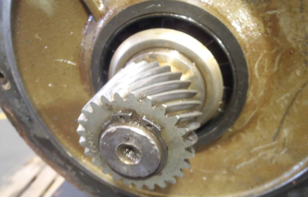
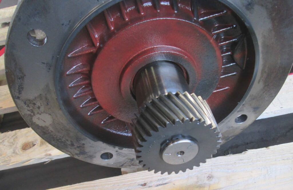
Helical gear attached to the end of the shaft
Some motors have a sheave or some kind of attachment on the shaft. Remove it first, especially if the bearings of the motor will be replaced.
Check the post, “How to remove a coupling, mounted gear, or pulley (sheave) from the shaft”
The basic tools you need to remove the attachment will be a bearing puller, a wrench, an Allen key if the attachment has a set screw, a snap ring remover if the gear is held by a snap ring, and a propane torch or oxy-acetylene torch in case it is tight.
Always measure the distance of the sheave from the end of the shaft so that you can put it back the same way.
If you have to use heat to remove the sheave, wear your safety glasses and protective gloves
Take pictures.
5. Remove the fan cover and the fan
Fan guard or cover of an electric motor
Not all electric motors have an external fan. Most totally enclosed motors have it and removing them can be straightforward.
Remove first the fan cover by undoing the bolts.
Cooling fans come in types and sizes. Check the post titled “Ways of removing the fan of an electric motor”.
The basic tool you need will be a pair of pry bars to remove the fan and depending on how the fan is held in the shaft, you might need a screwdriver, a snap ring remover, and a small socket wrench, or an Allen key.
6. Mark the end-bell (also called end shield, end cap, or end bracket) to the stator orientation
The Drive End (DE) of an electric motor refers to the end of the motor where the shaft drives the load.
The drive end shaft has load attachments which could be a sheave, a pulley, a gear, a coupling, or a blower fan.
The Non-Drive End (NDE) of an electric motor also called Opposite Drive End (ODE) refers to the end where the cooling fan of the motor is located. This is the end of the motor opposite the drive end
Most open drip motors don’t have a cooling fan or even a non-drive end shaft extension and so it’s closed but regardless, that end is called a non-drive end.
The end bell which is also called an end shield, end cap, or end bracket, is a part of the motor that covers both ends of a stator.
End bell also houses the bearings that support the rotor through the shaft called bearing housing. It helps to maintain the distance of the rotor to the stator core. This distance is called an air gap.
Reasons why electric motor stator and end bells are marked
The end bell to the stator must be marked because the stator core is not always in the middle of the stator housing which means if the rotor is installed backward, it will not be aligned with the stator resulting in the motor drawing a high current.
Putting the drive-end shaft to the non-drive end of the stator will also position the J-box (also called connection box, terminal box, or peckerhead) of the motor on the wrong side.
Installing the end bells upside down will put the grease nipples and sometimes the vent holes in the wrong spot.
The end bell and the stator are marked so that they can be assembled back the same way as it was. These are the ways the end bell and the stator are marked.
3 ways of marking the stator and end bell orientation
One punch mark on the non-drive end and two punch marks on the drive-end side
Two punch marks on the non-drive end and three punch marks on the drive-end side which we always do at the shop.
N letter punch mark on the non-drive end and D letter punch mark on the drive-end side
A paint marker is not advisable since it can come off anytime the parts are washed or cleaned with solvents.
Electric motors can have a double shaft like for example a shaker motor where both shaft extensions have the same diameter. In this case, it doesn’t matter which end is assigned as the drive end as long as they are marked.
7. Remove all the bolts fastening the end bells (end shield or end cap) to the stator.
The plastic cooling fan of an electric motor
There are different ways the end bells, also called end shields or end caps, are secured to the stator housing.
End bells directly bolted to the housing
Using through-bolts passing through inside the stator
Using through-bolts passing through outside the stator
Sometimes the bolts on one end are longer than the other. Take note of this so that you can put the proper bolt to where it is supposed to be.
Through bolts are also installed so that the nuts are on the drive-end side of the motor. Some manufacturers do this for a reason so put them back the same way.
Some bolts can be super rusty so it would help if you soak it first with an oil penetrant.
Use a parts bin so you won’t lose any parts. Be organized.
8. Removing bearing cap bolts from the end bells (end shield)
A bearing cap also called a bearing back cap, is a restraining plate installed at the back and sometimes at the back and in front of a bearing of an electric motor to ‘locate’ one end of the shaft while providing sufficient room in the other end for thermal expansion of the shaft.
The bearing cap ‘locates’ or held the bearing captive in the housing (usually the DE) to prevent axial displacement or movement of the coupling.
If there is a bearing cap you will not be able to remove the end bell from the shaft not until you remove the bearing cap first.
Two bolts on the end bell close to the shaft are an Indication that there is a bearing cap.
Sometimes both the DE and NDE end-bell have a bearing cap.
The bearing is locked in place on some motors using an internal snap ring right at the bearing housing.
The internal snap ring locking the bearing to the end bell can only be accessed once the rotor with the end bell still attached to it is removed from the stator
Some smaller motors have a bearing retaining ear instead of a back cap or snap ring to hold the bearing in place. Like the end-bell with the bearing held by a snap ring, it is easier to separate the endbell from the rotor if they are out of the stator.
9. If both end bells have back cap bolts, remove the non-drive end (NDE) back cap bolts first
There are advantages to removing the NDE bearing cap first although to some it doesn’t matter.
First is if you remove the NDE end-bell and the bearing housing fit is snug, the rotor will come with it which is annoying on bigger motors especially if you have to remove the rotor using a lift later.
Second, if the motor has an internal fan, it can be either on the drive end or the non-drive end of the shaft.
If the rotor comes with the endbell when you remove it, the internal fan will hit and can damage the windings of the motor.
10. Removing the NDE end bell also called end shield or the end cap.
End Bells are still held in two spots even after all the bolts are removed. One is on the stator rim and the other on the bearing. If the endbell clears these two, then it’s off the stator.
The usual way of removing it is by using a pry bar. On a very small motor, two flat screwdrivers are enough.
When prying the end bell, make sure to keep the tip of the pry bar from touching and damaging the windings.
8 ways to remove an end bell from the electric motor housing
Some motors have an opening notch between the end bell and the stator to accommodate the pry bar to pry an end bell off.
Some motors have cooling fins. Use the gaps between the stator and the end bell fins to pry and separate the two.
End bells have ears to accommodate the bolts. Tap this ear to rotate and be aligned with the feet of the motor or the fins of the stator and pry it from there
Another way is to use a dull chisel or a flat steel drift to tap and separate the end bell from the stator. Once an opening is made and the pry bar can fit, start prying the end bell out.
On smaller motors that don’t have a back cap, you can tap the shaft using a dead blow hammer in the direction of the end bell you want to remove. The dead blow hammer is made of polymer plastic and it will not damage the shaft.
Use a steel hammer and a piece of wood to protect the shaft if a dead blow hammer or any kind of mallet is not available
On smaller motors, if you remove the end bell and the rotor comes with it, that’s fine but make sure that there’s no internal fan on the other end. Or else you will be damaging the windings.
Some end bells are hard to remove especially when the bearing is seized inside the bearing housing. You can use a three-jaw puller for this job
Take your time.
11. Removing the DE end bell and the rotor of an electric motor
The rotor of an electric motor can be removed with the end bell still attached to it or without it.
The end-bell is removed first on bigger motors because a longer shaft extension is needed as leverage to remove the rotor out of the stator.
On smaller motors, if you remove the end bell and the rotor comes with it, that’s fine because there could be a snap ring holding the bearing inside the housing.
5 steps in removing the rotor and the end bell (end cap) of an electric motor with a bearing retaining snap ring
Removing the internal snap ring using a snap ring plier
Electric motors can have an internal snap ring inside the housing of the DE bearing instead of a back cap.
Bearings are held in place so that end play is minimized. Most roller motors have this as well as gearbox motors where the shaft cannot move back and forth.
Separate the end bell from the stator prying or tapping the other end of the shaft. See “5 Ways to remove an end bell from electric motor housing “
Once an opening is created, grab the top of the end bell with one hand and the shaft with the other and slowly remove the rotor out of the stator. Avoid hitting the windings.
Place the rotor upside down on a vise or similar stand.
Using a suitable size of internal snap ring plier, remove the snap ring.
Set the rotor on a piece of wood to protect the shaft and tap the end bell all the way around using a mallet until it separates from the rotor.
11 steps to remove the rotor and end bell of a capacitor start single phase motor
When removing the rotor and the end bell of single-phase motors, there are connection wires of the centrifugal switch that needs to be taken care of.
Some enclosed motors also have an internal fan opposite the centrifugal switch that you should mind.
Also, most centrifugal switches are on the non-drive end of the motor. Here is how you do it.
Remove all the through bolts and the fan if there are.
On a motor with a closed non-drive end (NDE) end bell, tap the drive end (DE) shaft with a mallet just enough for the NDE end bell to separate from the stator.
Using two pry bars or bigger flat screwdrivers, remove the end bell.
Using a needle nose or a long nose plier reach for the wire connectors and remove them from the switch.
Remove the NDE end bell.
Tap the shaft going the opposite way which is DE.
As soon as the end bell separates from the stator, grab the end bell with one hand and the shaft with the other and slowly remove the rotor.
On motors with an outside fan, most of the time you can just tap the NDE shaft using a drift or center punch until the fan, the rotor, and the DE end bell all separate from the stator.
Remove the rotor with the DE end bell still on it
In the process of removing the rotor, be careful not to bump the rotary switch to anything to avoid damage.
Then pry off the NDE end bell and remove the wiring connectors.
13 steps to remove the rotor and end bell (end cap) of a three-phase motor
Remove the fan covers and the fan of the motor.
Put punch marks on the end bells and the stator
Remove all the bolts securing the end bells
Remove the NDE end bell. See “5 Ways to remove an end bell from electric motor housing “
If the rotor comes out with the end bell, that’s fine, slowly pull the end bell until the rotor is halfway off the stator
Grab the rotor with one hand and the end-bell with the other and slowly remove it from the stator.
Pry the other end bell off.
If the NDE end bell comes off by itself, the next is to pry off the DE end bell. Again if the rotor comes with it, that’s fine. Slowly remove them from the stator.
Put the rotor with the end bell upside down on top of a block of wood and tap the end bell with a mallet until it separates.
Another way is while the rotor with the end bell is upside down on a block of wood, lift it then let it drop on the wood. The end bell should drop down.
On a larger motor with a heavier rotor, the end bell should come off when you pry it.
If the rotor is too heavy to manhandle, and your intention is just to replace the bearing, don’t remove the rotor. Remove and replace the bearing with the rotor on the stator then assemble it back together
If you have to remove the rotor, follow the steps in removing a heavier rotor out of the stator.
9 steps in removing a heavier rotor out of the stator
The rotor of a bigger motor, say between 25 HP to 100 HP motor might not be safe to remove from the stator even with two persons without a crane.
Some shops use a rotor lifting device to remove big rotors out of the stator.
If you have a chain hoist or a chain block handy, you can safely remove the rotor yourself. If the rotor is too heavy, you need them to support the weight of the rotor while removing it.
A hydraulic engine hoist or lift also will work.
Holding the DE shaft extension, pull the rotor out of the stator about a third out
With a sling rated at 3600 lbs. minimum, put a chokehold on the rotor
Using a chain hoist, lift the rotor until the weight is off the stator
Pull the rotor again until the haft of the rotor is out of the stator.
Let go of the chain hoist making sure the rotor is not touching the windings of the motor
Adjust the sling further to about a third the length of the rotor.
Lift the rotor again using the chain hoist until the weight is off the stator
While putting downward pressure on the shaft extension, slowly pull the rotor out of the stator. Keep the rotor from touching the windings.
If you need more leverage, insert a longer steel pipe on the shaft extension then put downward pressure on the pipe
Wear your safety shoes!
Conclusion:
Do you have a motor that you want to disassemble but are intimidated by the size or worry that you won’t be able to do it? You don’t have anything to lose so I would say go for it.
If you’re not successful you can always bring all the parts you disassembled to a shop and fix it for you.
It’s worth the try. Take lots of pictures. Work safe.
Electric motor burnout happens when the insulation materials used in the motor burn due to the overheating of wires or copper windings inside the motor.
These are the factors that cause overheating and burning of an electric motor. The following are also the reasons why amps go so high beyond what is written on the nameplate.
1. Overloading the motor
2. Single phasing of power supply
3. Wrong motor connection
4. Motor component failure
I also Include:
What burns inside the motor when it overheats
What happens when the motor is overloaded.
Steps to prevent electric motors from burning due to overloading.
What happens inside a 3-phase motor when it runs on a single-phase power supply by mistake.
Ways to prevent the motor from burning due to ‘single phasing’ of the power supply.
Factors that contribute to the motor being connected wrong
What happens when a Wye connected motor is hooked up to Delta by mistake
Ways to prevent electric motor burns due to wrong motor connection.
How the single-phase motor starting works:
What will happen when the motor runs without the starting winding.
Ways To Prevent Electric Motor Burns Due To Failure Of Its Electrical Component
Difference between Over-current protective device and Thermal protective device
In this post, you will learn how and why electric motor burns and how to avoid them.
Let’s start with what’s burning.
Inside the motor are coils wound using magnet wires or insulated copper wires. These wires are sized according to the horsepower of the motor and the full load current it draws.
So what happens if the amps are too high?
When the electric motor draws a current way more than its nameplate rating and exceeds the ampacity or current-carrying capacity of the wires used in the windings, it overheats.
This over-current condition takes place when the motor is operated beyond what it is designed to operate and do.
You cannot go over the rated amps without damaging the insulations inside the motor.
Overload protection is set at 125% of the rated current, so the motor can be subjected to that increase in amps but only momentarily. A few seconds.
Motor winding insulation can only handle certain temperatures depending on the insulation class.
Insulations within motor windings susceptible to burning are:
Insulation between wire turns
Insulation between phases
Insulation between the windings and the steel laminations inside the motor
Insulation coating of the copper wire
These insulations will fail if subjected to temperatures above their rating. For example, an electric motor with class F insulation can withstand 155˚C of heat as per NEMA standards.
When conductors overheat, the temperature reaches 400˚C and up. This is enough to burn these insulations.
Motor failure is costly not only in terms of having your motor repaired or replaced but also losses in terms of production output or product delivery, manpower hours, and lost profit.
Knowing these reasons and taking preventative measures makes electric motors last longer and is beneficial in the long run.
In this article, I will provide you with information on how each of these reasons affects your motor and how to prevent it from happening.
Let’s have a look at number one.
1. Electric Motors Burns Because Of Overloading
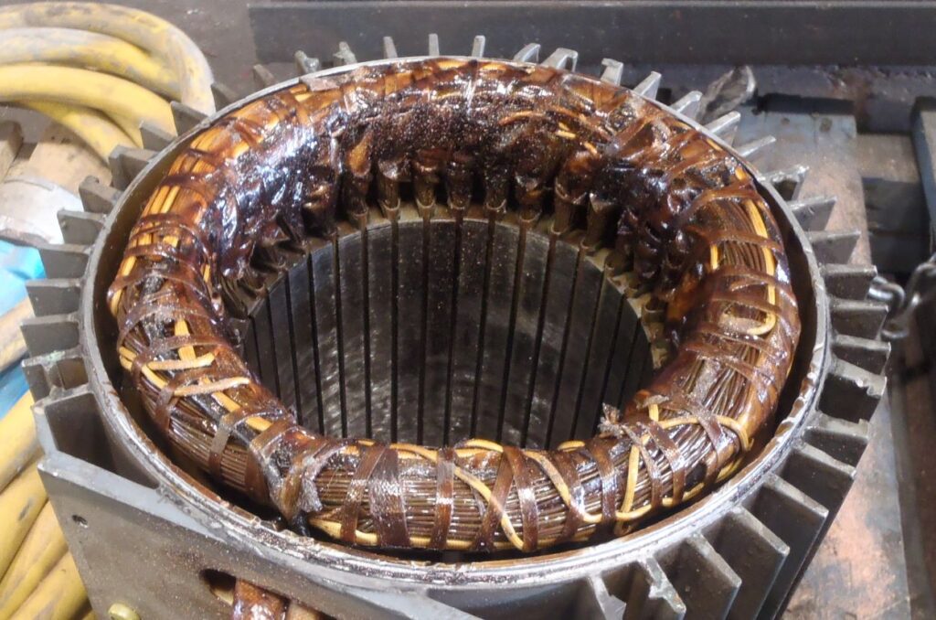
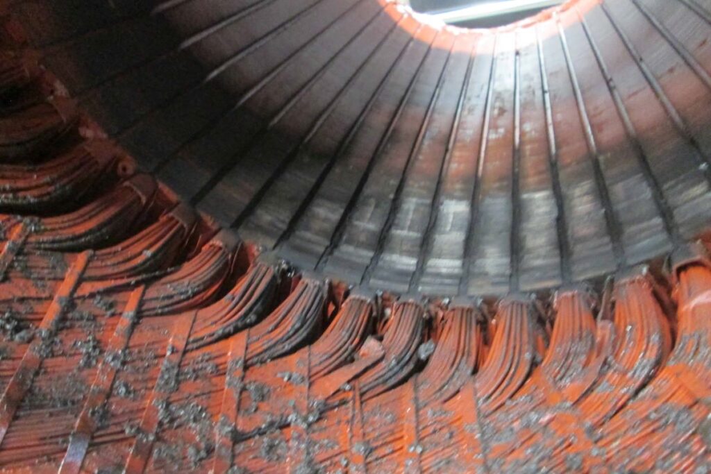
Motor windings and all its insulations burn evenly during overload
Motor overloading happens when the load applied to the shaft of the motor becomes greater than the output torque of the motor itself.
These are what’s going to happen when the motor is overloaded.
a) The current will go past the rated amps
b) The motor produces an abnormal humming
c) Rpm or the rotation of the motor at times will go a bit slower
d) Clicking sound inside a single-phase motor because of starting switch kicking in and out.
e) Frequent tripping of a circuit breaker or motor overload protection.
f) The increase in amps, when it goes beyond the current-carrying capacity of the windings, will result in damaging heat
g) The heat created by the motor coils deteriorates and burns the insulation of the motor windings
e) The motor smokes and burn
f) What happens inside the motor when it is connected wrong.
From the formula;
Torque=(Volts x 1.732 x Efficiency x Power Factor x 5250) / (RPM x 746)
Torque is directly proportional to the current and inversely proportional to RPM or speed of rotation. A 5 horsepower, 1750 rpm motor can only produce 15 pounds foot of torque.
If the torque required to turn the motor shaft increases and is beyond what the motor can deliver, the rotation decreases, and the current increases. This increase in current burns the motor.
Examples of ways a motor can get overloaded and burn:
Steel bar pressed too hard on the stone of a pedestal grinder
Saw blade jammed on the wood or steel it is cutting
Hardened chemicals at the bottom of the agitator
Dough too thick for the mixer
hard material stuck in the pump impeller
Pressing the cut-off saw too hard
Steps to prevent electric motors from burning due to overloading:
Overloading is preventable though some are just bound to happen. Lack of maintenance doesn’t help either. Here are some suggestions on how to prevent motor failures due to overload.
1. Use the motor protection device that comes with the motor
2. When buying a new motor or sending one for repair, request that a protection device be installed and have the electrician hook it up during motor installation.
3. Use a magnetic contactor that has a thermal overload relay
4. Do regular inspection and maintenance not only of the motor but also the equipment it runs.
5. Follow proper operating procedures of types of equipment.
6. An infrared temperature scanner is cheap. Use it to detect over-heating motors
7. Do not disable the overload relay or other motor protection. These devices trip for a reason so find out why
8. When fuses or circuit breakers trip, don’t replace them with a bigger one. It’s very dangerous
9. When production and load requirement has increased over time, consider upgrading the motor
10. Do regular maintenance not only of the motor but also the machines they are running because that is the source of the overload. Most often the motor is fine.
Maintenance not only of the motor but also the equipment it is running reduces the amps to an acceptable level and will also make the motor runs cooler. This includes:
Regular overhaul of the motor
Properly greased or lubricated bearing and pillow blocks of equipment the motor is running
Regular maintenance and cleaning of the equipment like fans. conveyor rollers, contaminant build-up, clogged chutes, etc.
Protecting the motor from water
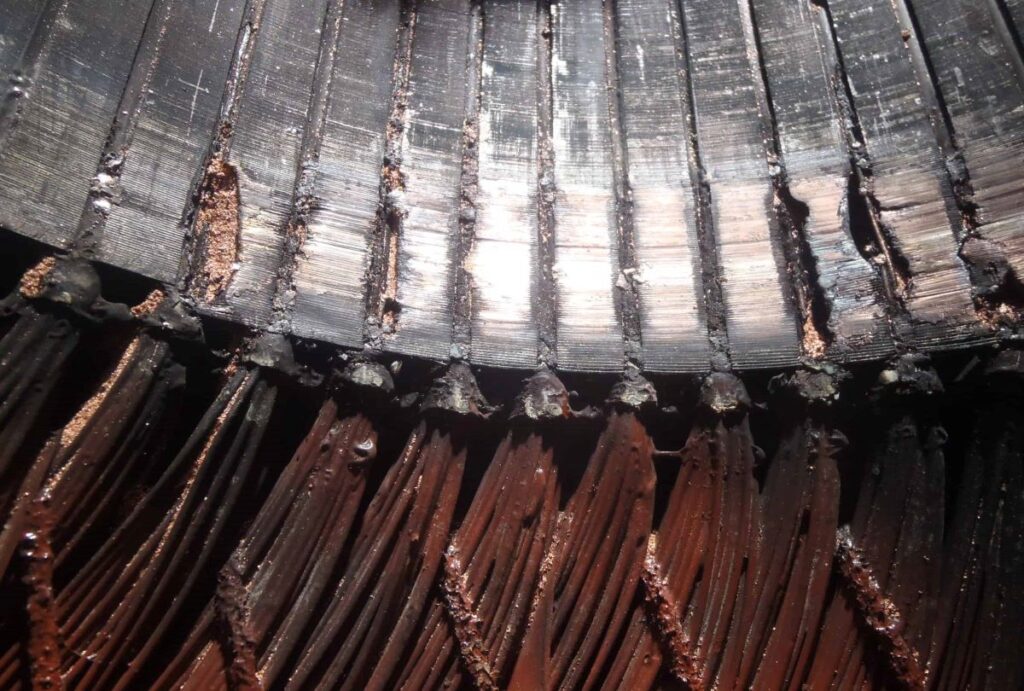
2. Electric Motors Burns Because Of The “Single Phasing” Of The Power Supply.
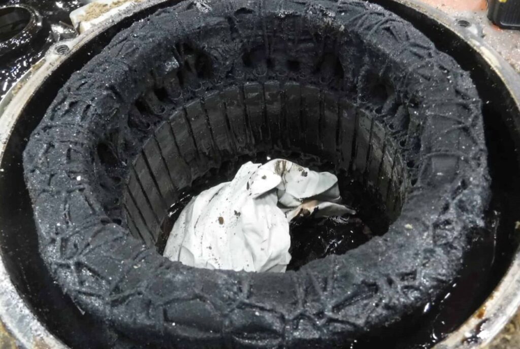
Motor failure due to single phasing leaves some portions of the winding unburn
Three-phase motors have 3 sets of winding coils supplied with 3 lead cables each of which is carrying voltage.
If you lose power on one of the cables, depending on the motor connection whether WYE or Delta, one or two sets of winding will burn inside the motor.
This is because the motor is trying to run the load using only a part of its winding.
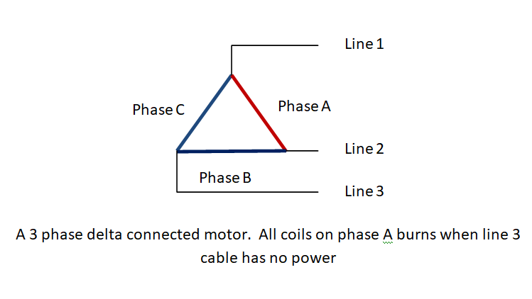
In this figure, when the power on line 3 for some reason dropped out, only phase A is experiencing full line to line voltage.
At full load, it will be impossible to run the motor with only one phase fully functional. The result will be:
a) The motor will not run
b) Humming noise is very pronounced
c) Current will be a few times higher than normal on two lead cables
d) The wires of the motor winding will be red hot
e) Insulations inside the motor burns
f) Smoke starts to appear from the motor
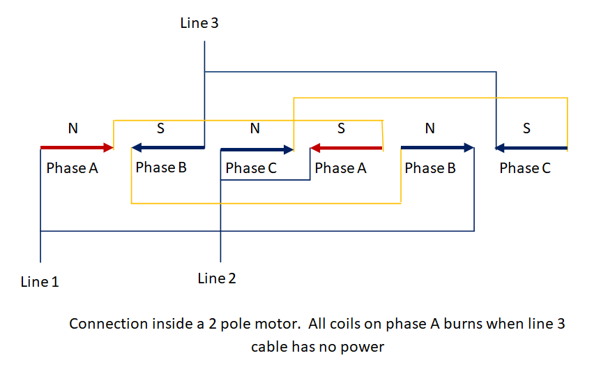
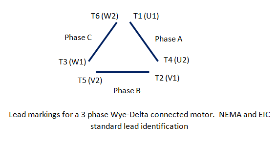
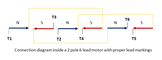
This figure shows the winding connection inside the motor. Polarities are shown by the arrows and the proper layout of the three phases. Yellow lines are used to connect a group of coils on the same phase.
If the cable of line 3 is disconnected, only phase A is energized with the full voltage. Only the coils colored red are experiencing the actual voltage.
And again, since the rotor is locked, the current will shoot up creating heat that will burn the insulation on that group of coils.
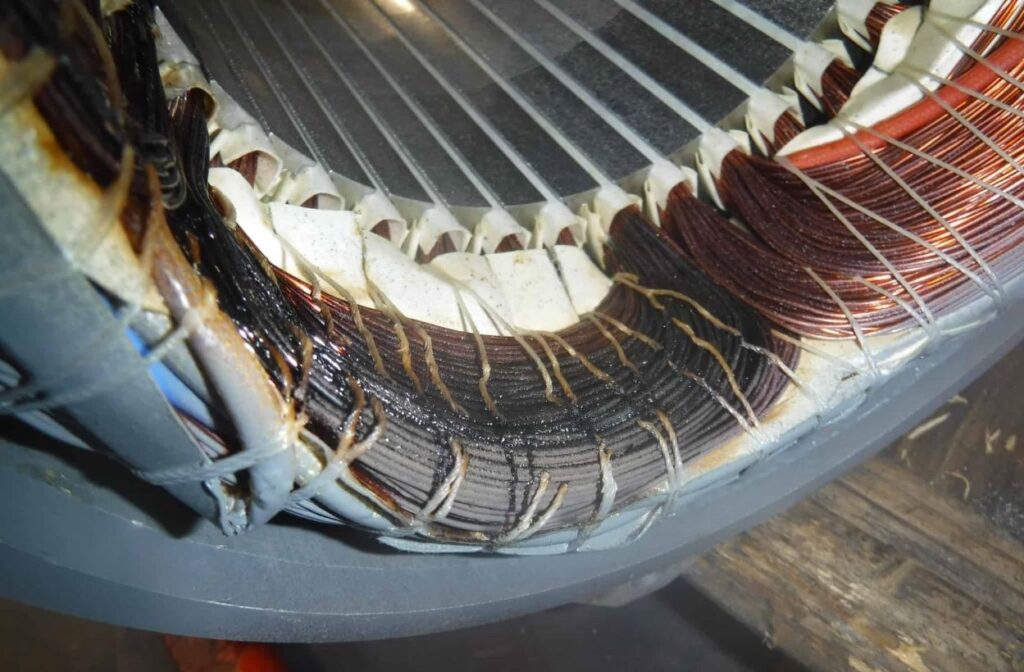
This is why on ‘single phasing’ when you look at the actual winding, you will notice a pattern of overheated coils. In this example, it will be burnt – good – good – burnt – good – good.
Repair shops can tell right away if the particular motor fails on “single phasing’ or not. If it did they will deny you a warranty even if the motor is brand new because it is the customer’s fault why the motor failed.
To prevent the motor from burning due to ‘single phasing’ of the power supply;
1. Do a regular inspection of connections. Check for the following:
a) Inside the motor terminal box, look for signs of over-heating connection screws. Tighten if necessary.
b) On the magnetic contactor inside the motor control panel look for signs of over-heating connection terminals. Loose terminal screws create high resistance contacts that produce heat.
c) If the magnetic contactor shows dust contamination, clean them with contact spray cleaner or very light compressed air.
2. If it is economically possible, replace the fuse disconnect switch with a 3 phase circuit breaker. Most of the time, the disconnect switch blows only one fuse leaving the motor susceptible to ‘single phasing’.
3. If the motor is plugged in a three-phase receptacle, make sure it is securely plugged and “twist locked”
Warning: Inspections of motor and control units must be done while all the main circuit breakers and fuse disconnects are in the OFF position to avoid shock hazards.
3. Electric Motors Burns Because Of Wrong Motor Connection
Three-phase motors have three sets of windings connected into a circuit or circuits of either Wye or Delta to in order run. It could be one circuit, two circuits, four circuits, and so forth. You cannot just put these three sets of winding in parallel and expect it to work.
All the windings of the motor are equally divided and distributed to the three phases of the power supply namely phase A-B, phase B-C, and phase A-C, so they will have more or less equal resistances.
The marked leads of the motor have to be connected properly at the j-box or terminal box. You miss the right connection and the motor will burn.
The following contribute to the motor being connected wrong:
Illegible or no motor lead markings
Illegible or no nameplate
Absence of connection diagram
a) Illegible or absence of motor lead markings or identification can lead to a wrong motor connection that will eventually burn the motor.
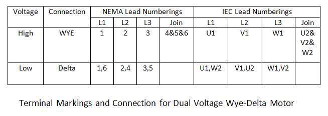
For example, a 5 HP, 460 volts, 1725 rpm motor has 6 leads with no markings or some color codes. We know from the electrical diagram that the end of T1 is T4, the end of T2 is T5, and the end of T3 is T6. For the IEC standard, the end of U1 is U2, the end of V1 is V2 and the end of W1 is W2.
The first figure shows the standard numbering of a Wye-start Delta-run motor. Let us say we have a motor to be connected but doesn’t have lead markings.
Looking at the diagram, since we know which leads are for Phase A, B, and C, we assign T1, T2, and T3 respectively on them. After that, we label the opposite of T1 as T4, the opposite of T2 as T5, and the opposite of T3 as T6.
If the lead numbering on any of the phases is interchanged say T1 to T4 and T4 to T1, there will be bucking of polarities, and soon as the motor runs, the current shoots up, and the motor burns.
The same is true with a 9 lead or 12 lead motor. The numberings and connections have to be right.
This figure shows the connection diagram with the correct lead marking.
When Line 1 of the power supply is connected to T1 and T6, Line 2 to T2 and T4, and Line 3 to T3 and T5, It illustrates the right flow of alternating north and south magnetic field on every coil inside the motor.
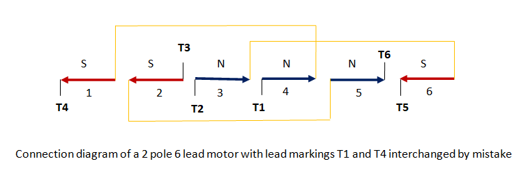
This last figure shows when T1 and T4 are mistakenly interchanged.
When the motor is connected wrong, these will happen;
a) The coils will create “bucking” of coil polarities, as shown on coils 6, 1, and 2 or coils 3, 4, and 5.
b) The shaft will either seize or turn slow,
c) The motor will create an unusual humming sound,
d) The current will shoot up way beyond the rated amps.
d) The coils inside the motor will eventually overheat burning the insulations.
b) Illegible or absence of a nameplate creates confusion on the part of the installer and gets a higher chance of mistake in connecting the motor wires to the power supply.
For example, a motor with 6 lead cables all numbered T1 to T6. The motor also has either worn out or no nameplate. The problem is, that other kinds of motors like two-speed variable torque, constant torque, or constant horsepower are numbered T1 to T6 also.
The same with a Wye start-Delta run a motor or a dual voltage Delta-Wye motor all have the same lead numberings T1 to T6. Without the nameplate, it is harder to figure out what the right connection is.
Let us say we have a motor with the following condition:
The nameplate voltage is unreadable
The electrician knows that the motor works at 460 volts 3 phase.
The lead numberings are T1, T2, T3, T4, T5, and T6.
It was assumed that the motor is 460 volts, 3 phase, 60 hertz
Because of this information, the motor was connected delta across the line.
If the motor is a single voltage, the motor will work because it is a Wye start-Delta run the motor. But we don’t know.
What if by chance the motor is 380/460V dual voltage which is a possibility? The motor has to be connected to WYE to work properly. This is because, on a dual voltage 6 lead motor, the connection should be Delta for a lower voltage and Wye for a higher supply voltage.
But then the motor was connected delta and the motor overheated. They thought it was overloaded.
On a dual voltage 6 lead motor, this is what happens when a Wye connected motor is hooked up to Delta by mistake:
First, the right connections should be Wye for higher voltage and Delta for lower voltage. Example 380D/480Y
Since it was connected delta, the motor was given higher across the line voltage instead of the lower value
There is an overvoltage condition when the motor is run.
At full load, the motor will experience saturation current
The increase in current will lead to overheating of the windings inside the motor eventually burning the insulation.
c) Absence of a connection diagram also leads to burning a motor. There is no problem connecting the motor, especially the basic ones like 12 lead motors, 9 lead motors, Part Winding Start motors, or even 6 lead Wye start-Delta run motors.
On the following motors, you might need a connection diagram to hook up the motor leads.
o Triple Rate or Three Horsepower- Two Winding motor
o Triple Rate or Three Horsepower-One Winding motor
o Two Speed-One Winding motor
o Two Speed-Two Winding 9 lead motor
The reason for this is that some manufacturers have their version of how to connect their motor depending on how it was connected on the inside of it. You are running the risk of burning the motor if they are not connected right.
Ways to prevent electric motor burns due to wrong motor connection:
Pay attention to the nameplate information when hooking up a motor. Indications that you have to be careful connecting the motor are:
When there are two or three horsepower
9 or 12 leads that might indicate that it can be a Wye or a Delta connected
When the motor is rated at 120 cycles per second, or anything other than 50 or 60 hertz
When you have a two-speed or three-speed motor with multiple leads
When you have a two speed motor with 8 leads it means you have a center tap for the brake
On new installs, use a clamp-on ammeter to monitor the current the motor is drawing. A value above the rated current especially at no load is an indication of a wrong connection.
Check the actual supply voltage and don’t guess. It has to be the same as the nameplate voltage of the motor.
4. Electric Motors Burns Because Of Failure Of Its Components.
Some examples of these components are:
Starting switch assembly
Starting capacitor
Motor overload or over-current protection protection
Motor cooling blower
1. Starting Switch Assembly
A single-phase capacitor start induction motor has two sets of windings, a starting winding, and a running winding.
The inductive property of the running winding makes it unable to run by itself. So, a starting winding with a lesser number of turns and smaller wire size is added or wound on top of the running winding inside the motor.
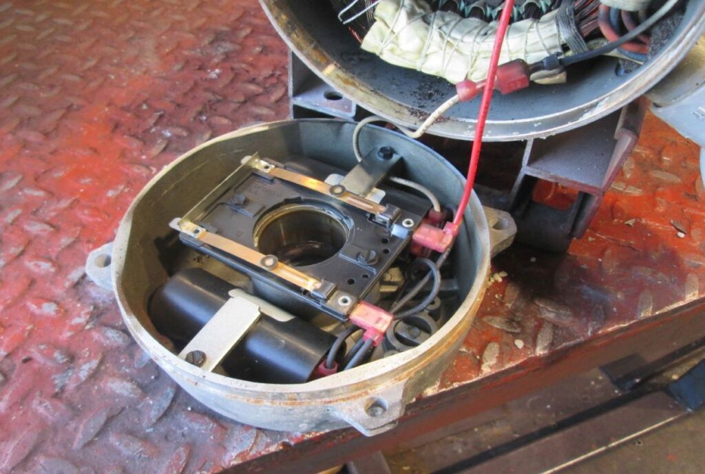
Starting capacitor and stationary switch mounted on the motor end shield
This is how the single-phase motor starting works:
a) When the motor is energized both the main or running winding and the auxiliary or starting winding will operate
b) The starting winding, with the aid of a capacitor, creates approximately 3 times the torque of the running winding. It will then run until it comes 3up to speed.
c) Although it has the torque suitable for starting the motor, it cannot run continuously or it will burn.
d) A centrifugal switch is connected so that soon as the motor reaches 75 to 85% of the speed, it will disconnect the starting winding leaving the main winding running the motor.
e) The centrifugal switch wears out over time and if they fail, will eventually burn the motor windings. The centrifugal switch has two parts:
Several times I have seen a motor with a broken rotating switch disc. If they break, it jams onto the stationary switch breaking the contact mechanism. But most of the time, it is the contact in the stationary switch that wears out.
The constant stop and go for example of an air compressor creates arcing on this contact point. Sometimes they just fused together keeping it from opening the starting circuit.
If the switch doesn’t cut the starting winding out, It will burn the starting winding for sure.
Another case is when the contact point breaks or blew out. This is what will happen when the motor runs without the starting winding:
o The auxiliary circuit will always be open
o The starting winding will not function
o The result is that only the main winding is energized
o Motor will just hum unable to rotate the shaft and eventually burning the main winding.
2. Capacitors
A worn-out or defective capacitor can also hinder the normal operation of the starting circuit. Its job is to suppose to help the starting winding produce the needed torque to start the motor by making the current through auxiliary winding lead the supply voltage by a considerable angle.
This is what will happen if the starting capacitor is defective:
a) There will not be enough torque to start the motor
b) The motor will just hum and will not rotate or if it is not fully loaded, the motor might run slow.
c) Since the motor doesn’t come up to full speed, the windings will eventually burn
3. Motor Protective Devices
Motor protection stops the motor in events of winding overheating before it burns the windings.
Two kinds of motor protective devices are:
a) Over-current protective device – mounted either on the J-box of the motor or the load side of the magnetic contactor controlling the motor.
It employs a bi-metallic element or snap-acting bi-metal disc rated in amperes. As the motor experience the over-current condition, the bi-metal disk or element opens the power supply connection stopping the motor. After it cools down, the disc snaps back allowing the motor to run again.
b). Thermal protective device – mounted directly into the motor windings and their leads connected to the motor control circuit. When they sense a temperature above their preset setting, it opens the control circuit of the motor shutting it down.
Constant arcing wears out these devices. If for example it got stuck in a close position, the motor is already over-heating and the protection is still not responding.
Ways To Prevent Electric Motor Burns Due To Failure Of Its Electrical Component:
Proper testing and maintenance is the best way to extend the life of these electrical devices. They are not expensive, and if you have to replace them, it is just a small fraction of the cost of a brand new motor.
1. Check if the electric motor protective device is working properly by monitoring the current of the motor.
To do this:
a) Make sure the power to the motor is in the OFF position
b) Hook the clamp meter in one of the cables supplying the motor. Let it hang by itself.
c) Operate the motor and monitor the current.
d) If the amp is normal and the motor protection trips, replace the motor protection device.
e) The motor overload protection is good if the amps went way above the nameplate current and the motor protection trips. The motor is experiencing an overload condition. Find out why and fix the problem.
f) Soon as the motor cools down, press the red reset button either in the side part of the j-box of the motor or the small reset button at the magnetic contactor of the motor.
Note: Do not in any way disconnect or disable the motor protective device.
Warning:
Working close to energized cables or rotating machines is dangerous and should be done by a trained technician only.
2. Schedule regular maintenance of the electric motor. Every six months or yearly depending on how often a single-phase motor is running on and off.
To check these components, do the following:
a) Test the capacitor by using a capacitor tester or a multimeter that can test a capacitor. Check if the capacitance value in microfarad (μF) is within the range of what is written on the capacitor.
b) Remove the motor end shield and inspect the operation of the rotary switch. It should smoothly travel in and out if you press it with your finger. Check for any crack.
c) Inspect the stationary switch and check for burnt or worn-out contact points due to arcing. Use a smooth file or a grade 220 emery cloth to smoothen the contact surfaces.
Warning:
Disassembling a motor is a job for a trained technician. If you have to do it yourself, be sure that the motor is completely disconnected from the power supply.
Conclusion:
These are the four common reasons why electric motors burn. In short. Keep your current even and at bay and your motor will last longer.
Your motor protection is like a body thermometer that says “hey I’m not feeling well. Do something about it”.
I did not include the reasons like bearing failure, electrical surge, insulation breakdown, or winding contamination to name a few since it is more on coil blowing in the slot, phase to phase, or coil to coil short and not a complete burnout.
The more you understand your motor the more you know what to do.
In a perfect world so to speak, an electric motor bearing can function for a very long time outlasting the motor itself.
The perfect condition for the bearing would be: that it is free of contamination, close if not perfectly aligned shaft, within tolerance shaft journal and housing fits, well-balanced and almost vibration-free rotor, ideal amount and good quality of lubrication, axial and/or radial load within the limit, and motor not experiencing overheating or overload.
But most of the time something always comes up and because the bearing is an integral part of the motor, once it fails other parts are most likely to be affected too.
When the bearing fails these are the things that can happen:
Shaft Journal wears out or damaged and needs to be plated and machined
Bearing housing wears out and has to be re-sleeved and machined
Rotor rubbing the stator laminations caused damage to the windings.
Collapsed bearing that makes the motor unrepairable.
If the motor is noisy and you are suspecting that the bearing is bad, It’s easy to say just replace it with a new one. Take apart the motor, remove the old bearing, slap in a new one, reassemble, and ‘done deal’. But not so fast.
The proper approach in replacing an electric motor bearing is to:
Disassemble the motor
Remove the old bearings
Inspect the windings, and the core for any damage
Check if the housing fits are good
Check if the bearing journal is good
Inspect the old bearings for any telltale sign of why the bearing failed and learn from it
Replace the bearing with a new one
Apply lubrication
Reassemble the motor.
If we have a better understanding of the motor bearing and what it can do if we neglect it, we can avoid costly mistakes.
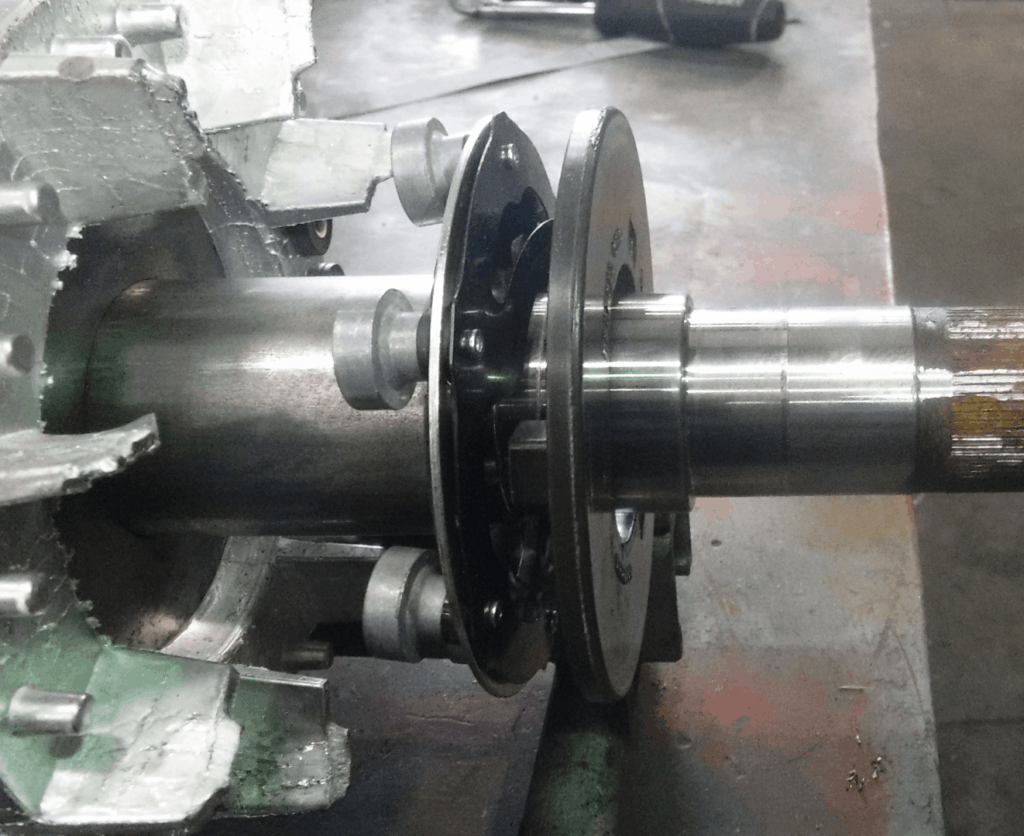
1. Electric motor bearing failure can wear out or damage shaft journals.
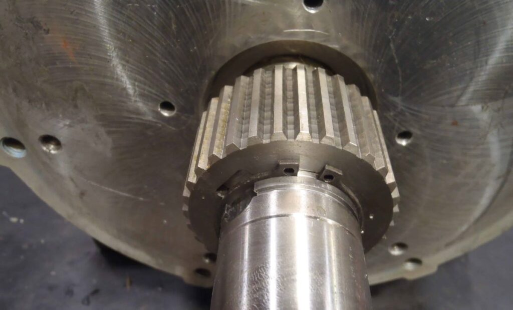
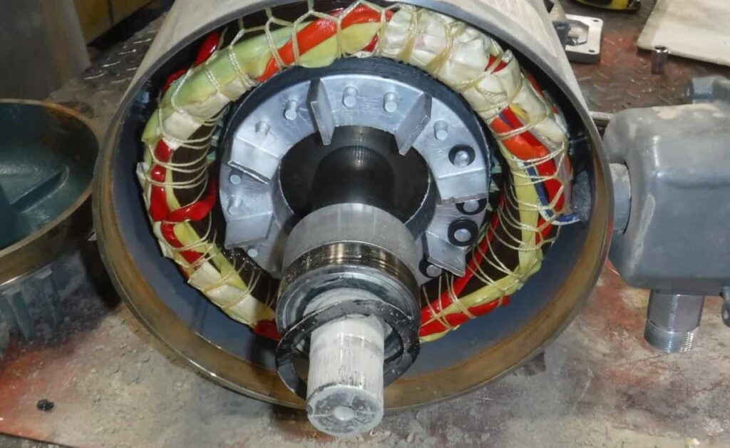
Bearing Journal Right Beside the Centrifugal Switch
Bearing Journal is the part of the shaft where the bearing is in contact or located.
It has an interference fit which means the shaft journal diameter is bigger than the bearing bore or ID of the bearing inner race.
The shaft diameter is 0.0001 to 0.0004 inches (0.00254 to 0.01016 mm.) bigger than the inside diameter of the bearing. That is the reason why you need a puller to remove the bearing out of it.
The bearing inner race that sits in the shaft is stationary and is not meant to spin. They have standard tolerances, except for some special applications, to keep from spinning.
So why in the world will the journal wear out if the bearing is tightly held in place? It shouldn’t not unless the bearing inner race moves. But it will move and spin only if the inner race diameter of the bearing expands bigger than the shaft journal.
The metal expands with heat therefore if the bearing is hot due to for example lack of lubrication, the inner race will spin.
This metal-to-metal friction combined with the heat will wear the shaft journal not to mention the noise it will create.
Since the bearing is made of high carbon steel which is very hard, the shaft is more likely to wear out.
If the shaft journal is 0.0001 inches smaller than the minimum allowed diameter, it is considered worn out and needs to be repaired. That is unnoticeably small so how do we know if the shaft is undersized?
Besides obvious marks like discoloration on where the bearing sits on the shaft or bearing falling off the shaft without using a bearing puller, the best way to know if the journal is bad is by measuring.
Use a micrometer to see if the shaft is any good. If you don’t have a micrometer, bring it to a machine shop and have it measured for you.
The following table shows the minimum and the maximum allowed diameter of the shaft journal for every specific size of bearing.
For example, the size of the bearing you removed from the shaft is 6205. The table shows that the shaft diameter should be between 0.9844 to 0.9848 inches.
If you measure the shaft and it is 0.9842 inches or smaller, it has to be repaired. But if it is 0.9850 or bigger, that diameter is over the limit so the journal has to be polished down to 0.9848. If not, it will be too tight and it will just create damaging heat.
Table: Bearing Journal Tolerances
200 Series
300 Series
Maximum
Minimum
6200
6300
0.3939
0.3936
6201
6301
0.4726
0.4273
6202
6302
0.5908
0.5905
6203
6303
0.6695
0.6692
6204
6304
0.7879
0.7875
6205
6305
0.9848
0.9844
6206
6306
1.1816
1.1812
6207
6307
1.3785
1.3781
6208
6308
1.5753
1.5749
6209
6309
1.7722
1.7718
6210
6310
1.9690
1.9686
6211
6311
2.1660
2.1655
6212
6312
2.3628
2.3623
6213
6313
2.5597
2.5592
6214
6314
2.7565
2.7560
6215
6315
2.9534
2.9529
6216
6316
3.1502
3.1597
6217
6317
3.3472
3.3466
6218
6318
3.5440
3.5434
Shaft Journal Fit Tolerances – NEMA Standard
How to repair a shaft journal.
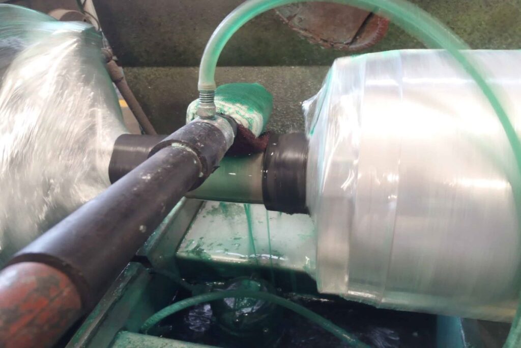
A worn-out or damaged electric motor shaft journal is repaired by Nickel or Chrome plating through an electrolysis process.
The rotor is mounted on a rotating machine but before going into the process, the shaft journal undergoes degreasing and then sandblasting using glass bead or silica sand while rotating to ensure proper adherence of the plating metal to the shaft.
Bearing Journal Repair by Plating
The machine where the rotor is mounted will serve as the negatively charged electrode and the wand with continuously flowing metal plating solution is the positively charged electrode.
This special wand allows the even distribution and build-up of metal to the specific part of the shaft while the rotor is slowly rotating.
All other parts of the rotor are taped or masked to avoid coating deposits on all other surfaces.
The diameter of the bearing fit is repeatedly checked until the build-up of metal is within the tolerance then it is lightly polished.
The length of time for the process is about 30 minutes to even hours depending on how thick the required build-up will be.
Other ways of fixing a worn-out shaft journal are:
Electroless nickel plating uses a chemical autocatalytic reaction to deposit the coating instead of electrolysis
Machining the shaft journal and building it up again by welding. Then it is machined back to the proper size. This allows a solid metal to metal bonding
The use of spray welding instead of the regular welding to build up the shaft journal before machining it back to the right size
Machining the shaft down and inserting a pre-machined sleeve. EZE Sleeve or EM Quik Sleeve are examples of the ready-made sleeve.
Of course, all of these repairs don’t come cheap. Buying a new one might be an option not unless the motor is special and pricy like a double shaft motor or threaded shaft.
A patch-up job offers a temporary fix to a worn-out shaft journal. It is not recommended but it can be used during emergencies until the replacement motor becomes available;
One way is to apply a dab of Loctite retaining compound before bearing installation. Just a small dab will do the work. Putting too much can contaminate the rolling elements of the bearing.
The downside of Loctite is that when the bearing overheats again, combined with vibration, this adhesive breaks down and the motor is back to the same situation.
Another way is by putting chisel marks or punch marks around the journal. Then the bearing is installed using a bearing driver.
Of course, again, these are just temporary fixes.
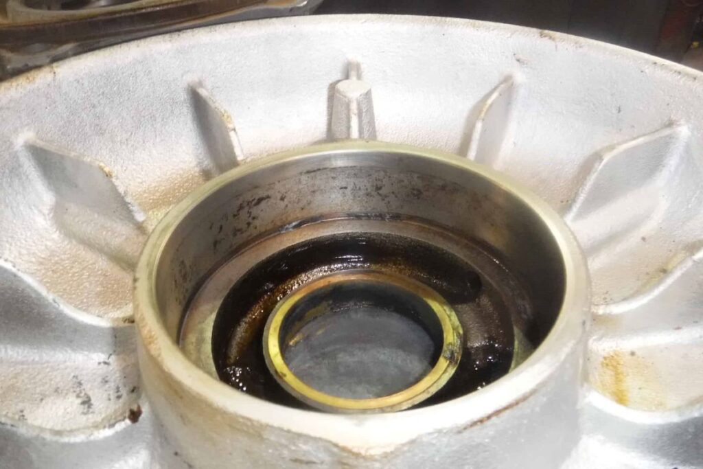
2. Electric motor bearing failure can cause housing to wear out or damaged
Bearing housing is a part of the electric motor end shield that houses the bearing. It has a sliding fit or also called clearance fit which means the housing diameter is slightly bigger than the bearing outer race or OD of the bearing.
Damaged Bearing Housing Visible Discoloration
For example, the housing diameter of a 6208 bearing is 0.0001 to 0.0008 inches (0.00254 to 0.02032 mm.) bigger than the outside diameter of the bearing to allow for bearing expansion.
That is the reason why you can remove the end shield from the motor by just prying it out or installing it by just sliding it in. Not unless there is a snap retaining ring holding the bearing in place inside the housing or the bearing is full of rust.
The bearing outer race that sits in the housing is stationary and is not meant to spin. They have standard tolerances to keep them from spinning as soon as they expand during operation.
Retaining compounds such as Loctite is not necessary for as long as the housing is within tolerance.
Excessive axial and radial load combined with the rise in temperature due to lack of lubrication wears out the bearing housing.
When the bearing housing wears out, the diameter increases allowing the bearing outer race to spin in the housing
This metal-to-metal friction combined with the heat will not only wear out and damage the housing but will also create a squealing noise.
Since the bearing is made of high carbon steel, the housing is more likely to wear out.
If the bearing housing is 0.0001 inches bigger than the maximum allowed diameter, it is considered worn out and needs to be repaired. That is so small, how then can we know if the bearing housing is bad?
Obvious marks of discoloration on where the bearing sits on the housing would tell that the housing is bad. If there is no mark of wear, the housing should still be checked.
One way is by using a test bearing. It can be a brand new or a slightly used bearing, the same size as the one you removed.
This is how to check the bearing housing using a test bearing.
1. Clean the bearing housing. Remove any grease and dust particles.
2. Remove rust if there’s any by using a scotch pad or fine-grit sandpaper. After cleaning, lightly smear it with any kind of machine oil
3. Clean the test bearing. It should be the same if not the actual bearing removed from the shaft. Don’t worry about the bearing being worn out because they are made of high-carbon steel. Dab it with a thin layer of oil.
4. Install the bearing to the housing. If you do it straight and not on an angle, you should be able to do it by hand. Use a rubber mallet and tap it all the way around if you need to
5. Using your index finger and thumb, try to wobble the bearing side to side. A good bearing does not show any visible movement between the housing and the bearing outer race. Do that in different locations around the bearing.
6. Again using your index finger and thumb, try to rotate the bearing. You shouldn’t be able to spin or even move the bearing inner race on a good housing. If it does, the bearing housing is worn out.
The more accurate way of knowing if the housing is good or bad is by measuring.
Use an inside micrometer to see if the housing fit. Again, if you don’t have a micrometer, I suggest you bring it to a machine shop and have it measured for you.
The following table shows the minimum and the maximum diameter of the bearing housing for every specific size of bearing.
For example, the size of the bearing you removed from the shaft is 6208. The table shows that the housing diameter should be between 3.1503 to 3.1496 inches.
If you measure the housing and it is 3.1497 inches or bigger, it has to be repaired according to the tolerances given on the table. But if the housing diameter is 3.1502 or smaller, that diameter is undersized so the housing has to be polished up to 3.1503.
Housing that is too tight for the bearing will only create damaging heat due to a lack of room for bearing outer race expansion.
Table: Bearing Journal Tolerances
200 Series
300 Series
Maximum
Minimum
6200
1.1816
1.1811
6201
1.2604
1.2598
6202
6300
1.3756
1.3750
6301
1.4573
1.4567
6203
1.5754
1.5748
6302
1.6541
1.6535
6204
6303
1.8510
1.8504
6205
6304
2.0479
2.0472
6206
6305
2.4416
2.4409
6207
6306
2.8353
2.8345
6208
6307
3.1503
3.1496
6209
3.3474
3.3465
6210
6308
3.5443
3.5433
6211
6309
3.9379
3.9370
6212
6310
4.3316
4.3307
6213
6311
4.7253
4.7244
6214
4.9223
4.9213
6215
6312
5.1191
5.1181
6216
6313
5.5128
5.5118
6217
6314
5.9065
5.9055
6218
6315
6.3002
6.2992
6219
6316
6.6939
6.6929
6220
6317
7.0876
7.0866
Bearing Housing Fit Tolerances – NEMA Standard
How bearing housings are repaired
Bearing housings are repaired by machining. This is done by installing a sleeve and then machining it down to the proper size. For example, you have an end shield that has a bearing size of 6209.
This bearing has an actual outside diameter of 3.3465 inches (85 mm.) and a depth of 0.748 inches (19 mm,)
Procedure:
1. From a steel pipe material, machine a sleeve with an outside diameter of 3.597 inches, an inside diameter of 3.297 inches, and a depth of 0.945 inches.
Chamfer cut one of the outside diameter edges.
2. Put the end shield also called the end bell on the four jaw lathe machine chuck and dial the machined outer edge.
3. Make sure that the face and the rim surface of the machined end bell edge are dialed to or close to zero.
4. Or, instead of the face of the end bell edge, you can dial the machined portion of the bearing housing which is parallel to the lathe machine chuck.
5. Machine the worn-out bearing housing down to 3.592 inches. Do not put any chamfer on this part.
6. With the chamfered side going in first, install the pre-machined sleeve into the bearing housing.
Tap it in using a steel or aluminum hammer. Do not worry about denting the edges of the sleeve. It will be machined afterward.
7. Dial the rim and the face of the end bell again to zero making sure it didn’t move during sleeve installation.
8. When the sleeve is fully inside the bearing housing, there will be an extra length of sleeve material sticking out. Use this portion to make a trial cut before proceeding with machining the sleeve.
9. Machine the bearing housing according to the tolerances given on the table for a 6209 bearing.
10. Machine off the extended portion of the sleeve and put a small chamfer to facilitate bearing installation. Done!
The machined housing’s diameter is 3.592 (91.2368 mm) while the sleeve is 3.597 (91.3638 mm). The sleeve is 5 thou (0.127 mm) bigger than the machined housing.
That clearance is important because if the fit is too big, the sleeve can warp but if it is too small, it can spin in the housing.
There are also other ways of installing the sleeve to the machined housing like freezing it using nitrogen and also by pressing it using either an arbor or hydraulic press, or the tailstock of the lathe.
Instead of machining a sleeve, ready-made ones are commercially available for example EZE- Sleeve or EM-Quik-Sleeve which are available in the market.
Although that in my opinion is the best way to fix worn-out bearing housing, there are other ways also. Some of them are:
a) Electroplating uses a nickel plating solution to deposit the metal coating through electrolysis.
b) Machining the bearing housing and building it up again by spray welding.
After the proper amount of metal build-up, it is machined back to the required size as indicated in the table.
c) Machining the bearing housing down and inserting a wavy tolerance ring.
d) Buying a replacement end bell for the particular brand and model of your motor.
Again, repairing a cheap motor may not be worth the time and money since electric motors nowadays are cheap, not unless the motor is special, pricy, or hard to find.
Temporary fix of the worn-out bearing housing.
I call it a patch-up job. It is not recommended but it can be used during emergencies until the replacement motor becomes available
1. One way is to apply a dab of Loctite retaining compound before bearing installation.
I recommend this only if the bearing housing is over by about 0.0001 to 0.0002 inches from the maximum tolerance given in the table.
Just a small dab will do the work. Again, putting too much can contaminate the rolling elements of the bearing.
Once again, the downside of using Loctite is that when the bearing overheats, combined with vibration, this adhesive breaks down and the motor is back to the same situation.
2. If the bearing housing is damaged already, you can patch it up by putting punch marks using a center punch around the housing.
The punch marks will create raised dents all around the bearing housing that will fit with the bearing a bit tighter.
A Loctite retaining compound can also be added to fill up the gaps.
3. Another way is by putting a knurl on the bearing housing. This is done by using a handheld knurling tool.
This will create crossed patterns with raised areas around the bearing housing that will make the bearing fit snug. Sometimes used in combination with Loctite retaining compounds.
Of course, again, these are just temporary fixes.
3. Bearing failure can cause the rotor to rub the stator causing damages
The bearings allow the rotor to spin inside the stator. Without the bearing that is not possible.
The magnetic flux on the stator will try to grab the rotor but because the bearing supports the rotor on both ends it will instead create a rotational magnetic flux to keep it spinning.
The gap is about 0.016 inches (1.5 mm). Maintaining that small air gap between the spinning rotor and the stator is important not only for the efficiency of the motor but also to keep them from rubbing with each other.
If the bearing and the housing get damaged, the gap closes in and the rotor will touch and rub the stator.
Damages caused by the rotor rubbing the stator:
a) Stator lamination fuses together creating damaging heat
b) The laminated steel of the stator dragged sideways can result in shorted motor windings.
c) Rotor causes damage to the top wedges exposing and shorting the wires causing blow-up.
d) Bad rotor damage might require laminations to be restacked
Stator lamination fuses together creating damaging heat
The stator of an electric motor is made up of layers of 0.020 inches (0.5 mm) thick silicon steel laminations, individually coated, then stacked together to form the core of the stator.
The coating between layers of the silicon steel creates an inter-laminate resistance that helps in minimizing hysteresis loss and eddy current or circulating current in the core.
These losses have to be kept to a minimum so that the core will not heat up.
Fused Stator Laminations When the Rotor Rubs the Core
When the rotor rubs the stator, these laminations are fused together creating what we call “hotspots “.
When the motor is running, heat is produced in that portion of the stator and it is enough to burn the insulation causing the wires to be shorted to the core-
The laminated steel of the stator dragged sideways can result In shorted Motor windings
The stator core of an electric motor is not one solid piece of metal. They are thin layers of laminated steel tens to hundreds of them stacked together to form the core.
The portion of the lamination closest to the rotor is called a stator tooth and the space between teeth is called a stator slot.
Coils or magnet wires are in these stator slots and they are prevented from touching the steel core using insulation paper.
When the rotor rubs the stator, the tooth gets dragged sideways pressing onto the insulation and the coil creating electrical shorts.
I see this happen on smaller motors where the tooth width is narrow. The thin edges of the laminations tend to damage the insulating papers protecting the coils.
Rotor causes damage to the top wedges exposing and shorting the wires causing blow-up.
Top wedges also called top sticks are inorganic high-temperature insulating materials like NOMEX by DuPont or CeQUIN by 3M.
They are insulating papers formed into wedges and inserted right on top of the coil to protect and keep it from coming out of the slot.
Most of the time they are situated close to the surface of the stator and when the rotor rubs into it, they get damaged and stripped. The exposed wires are then rubbed to the spinning rotor blowing up the shorted wires.
Bad rotor damage might require laminations to be restacked
A stator core is made up of tens to hundreds of thin laminated silicone steels stacked together to form the stator core.
These laminated steel called laminations are magnetically insulated from each other.
It is designed this way to minimize eddy current or circulating current in the stator core because of the lower core power factor, and watts per pound of the stator.
When the rotor rubs the stator badly, there will be a need to re-stack the core especially if the motor is irreplaceable, the motor is special, or the new motor delivery will take a while.
If besides the stator the rotor is also damaged, the motor will be scrapped. The motor is beyond economical repair
4. Motor with collapsed bearing makes it unrepairable
Neglect and inexistent motor maintenance result in bearing collapse. This happens when a portion or all of the bearing balls comes off from inside the bearing.
The extent of damage makes the motor unrepairable or at least economically. It could be a combination of damaged end shield bore, two bearing housings, one or two journals, damaged rotor bars, stator core needing re-stacking, and/or rewind. It can be very expensive.
Tips on how to avoid bearing failure:
1. Regularly check the motor performance.
A maintenance checklist indicating the motor identification, temperature, noise level, vibration, date, and remark will be best for this, especially in an industrial setting.
Any abrupt change is a telltale sign that the motor needs attention.
.
2. Regularly have the bearings replaced. Bearings are cheap compared to the cost of replacing or repairing a motor.
Once a year or every two years, have it overhauled and the bearings replaced especially if the motor is loaded to its max.
3. Avoid subjecting the motor to water or corrosive chemicals to avoid rusting. There is at least 0.001 inches gap between the shaft and the end shield bore so water and moisture can go in.
When the motor is warm from the operation and then it will be idle for some time, rust develops in the bearings.
4. Replace or lubricate the bearing at the sign of an increased level of noise.
A small magnetic humming and noise coming from the fan windage are normally expected on a motor. But more than that, the bearing has to be lubricated
Lubricating a motor that doesn’t have a grease nipple might be a challenge. So, having the bearings replaced is a good option.
Conclusion:
Most electric motor damages can be prevented just by keeping their bearings in good shape
As I said, brand new bearings are cheap compared to the motor, and don’t even consider repacking it. Not worth it.
When the bearing makes noise, the damage to its outer race is done.
A dual voltage Wye-Delta motor connection is most of the time mistaken as the same as a Wye start Delta run 6 lead motor. They are not. And although they have the same lead or terminal numberings, their application is totally different.
Most of the time, you can find this connection on IEC standard motors. Some NEMA standard motors like 2,300V/4160V motors have this connection too.
I’ll teach you how to connect a dual voltage Star Delta motor
1. Make sure that the circuit breaker or any type of disconnecting switch used is ‘OFF’.
2. Read the nameplate and confirm that the motor is dual voltage.
3. Measure the incoming voltage of the circuit breaker or disconnect with a multi-meter. Do it with caution.
4. If the incoming voltage matches or is close to the lower voltage indicated on the nameplate, connect the motor terminals to Delta.
5. If the incoming or supply voltage matches or is close to the higher voltage indicated on the nameplate, connect the motor terminals to Wye.
I’ll explain why each of the steps is important for safety reasons and at the same time avoid damage to your motor.
Step 1: Make Sure there is No Power going Into the Motor
Turn Off the power. These could be a disconnect switch, circuit breaker, ON and OFF switch or a fuse box.
Check the supply cable on the motor with a multi-meter and confirm if there is power.
Always be on the safe side. Never ask anybody to turn it OFF for you. Do it yourself.
Put a tag or a lock so no one accidentally turns it ON.
Step 2: Read the Nameplate Information
In the nameplate, it should indicate that there is only one Horsepower rating, one speed, one frequency rating but the voltage rating are two.
Examples of these are 230/400, 280/480, 480/830, 208-230/380, and some other IEC voltage configurations. 230 V is the low voltage and 380 is the high voltage.
Step 3: Check the Supply Voltage With Your Multi-meter.
This step is just for confirmation but if you’re absolutely right about the supply voltage, you might skip it. Motor Rewinding Solutions.com is concerned for your safety.
The supply side is the input voltage going into the circuit breaker, the three cables just before the fuses, or if you have a magnetic contactor, the input at the top of the unit.
Step 4: If the Supply Voltage Matches the Low Nameplate Voltage, Connect your Motor to Delta.
.
The reason for this is that the Line Voltage on a Delta connection is the same as the Phase Voltage ( V line = V Ø on Delta). The group of coils on every phase inside the motor are designed to handle the full Low Voltage supply
Step 5: If the Supply Voltage Matches the High Nameplate Voltage, Connect your Motor to Wye.
The reason for this is that the Line Voltage in a Wye connection is equal to the Phase Voltage X 1.732 (V line = V Ø on Wye). This means that at the Wye connection, the motor coils that are designed for Delta are able to stand a higher voltage of 1.732 times the Rated Voltage.
For example, a motor designed for 230 Volts Delta can be supplied with 380 volts when connected to Wye. With that said, don’t just pick a connection to wire a motor hoping that it will work. By chance maybe it will but you are also risking damage to the motor.
Can you connect a dual voltage 6 lead motor to a Wye-Delta starter?
If your motor is 7.5 HP or larger, there might be a need of using a Wye-Delta starter. The question is can you use this on a 6 lead dual voltage motor?
You can use a Wye-Delta starter on a 6 lead dual voltage motor as long as you use the low voltage rating on the motor nameplate. This also means that the low voltage rating of the motor matches the supply voltage.
For example, on a 230/380-volt motor, you can use the Wye-Delta starter on the 230 volt Delta connection. You will use Wye as the Starting connection and Delta as the Run connection.
What if the supply voltage is 380 volt? If the input voltage to the motor matches the high voltage rating of the motor, you have to connect it to Wye and you cannot use the Wye-Delta starter.
Alternative Starters If a Dual Voltage 6 Lead Motor is Connected Wye.
When the supply voltage requires you to connect the motor to Wye, you cannot use the Wye-Delta starter. But there are other alternatives. Some of the choices are:
Across the Line or Direct on Line
Reduced Voltage Starting
Electronic Soft Starting
Rewinding the Motor to Single Voltage 6 Lead Wye-Delta
Except for connecting your motor directly from the power source, all the other methods of motor starting may be more expensive but there are times when you just don’t have a choice.
If your motor failed because of frequent stops and starting and needs to be rewound, you can consider telling the repair shop to rewind the motor into 6 leads Wye-Delta using the high voltage rating.
For example, if your supply voltage is 460 volt and you have a 380/460 V motor for rewind, you can have it rewound for 460V 6leads Wye-Delta. It will be just a single voltage motor and this will work on a Wye-Delta Starter. Motor Rewinding Solutions is willing to give you the redesigned parameters but I need the original data of the motor windings.
How to Tell for Sure that the Motor is Dual Voltage?
You might say it is easy. Just look at the nameplate and if there are two voltages the motor is dual voltage.
A motor is considered dual voltage if the low nameplate voltage is 58% of the high voltage rating. If the nameplate has two voltages but the difference is only 10%, it is the range of allowable voltage that the motor can handle but not considered a dual voltage motor.
An example of this is a motor with a 530/580V nameplate voltage. This is considered a single voltage motor and should not be mistaken as a dual.
Why do the manufacturers do that? They designed the motor to handle a range of voltage so they can market it to countries with different supply voltages and still deliver the torque the motor nameplate says it will. A smart thing to do.
Is It better if the Dual Voltage Motor is Connected Wye or Delta?
Some confusion arises as to which connection is better when it comes to torque strength or efficiency. Although that may be true in the manufacturing side of the motor, for us end-users of the motor, there is no effect on the horsepower or otherwise efficiency if you connect it Delta or Wye. Here is the fact;
On a Dual Voltage Motor, as long as it is connected Delta on low voltage applications or Wye on the high voltage applications and the supply voltage corresponds to these voltages, the horsepower or the KW rating of the motor will be the same on both connections
The only advantage you can have is the privilege to use it on a Wye-Delta starter but this is limited to the use of the low voltage rating only.
Every motor is designed by the manufacturer to run on a specific type of connection and we cannot change that unless we redesign and rewind the motor.
On the Wye connection, the voltage per turn is smaller compared to Delta which means there is less strain on the wire insulation.
However, because the motor manufacturer wants to provide the customers with motors that have the ability to use Wye-Delta Starters, they produce Delta-connected motors. But that’s only one of the many reasons.
Connect a 6 lead Dual Voltage Motor into Wye or Delta Using this Table
Depending on what type of leads you have on the terminal box, you are supposed to connect a 6 lead dual voltage motor a certain way. This is the table on how the leads are supposed to be connected.
If the motor uses a terminal block on its connection box, be sure that the right lead numbers are joined by the brass links. Some leads are color-coded but you will still notice that T1, T2, T3, T4, T5, and T6 are printed on the leads.